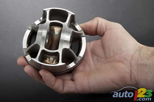
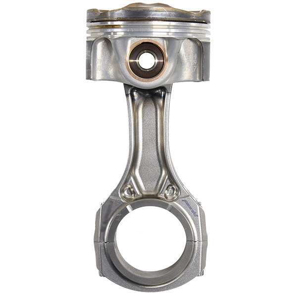
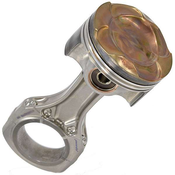
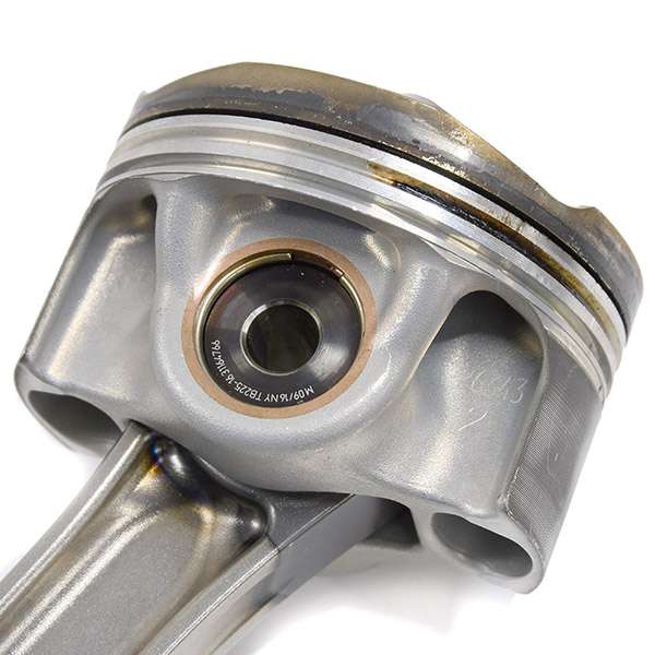
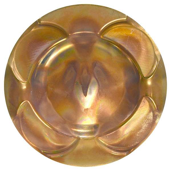
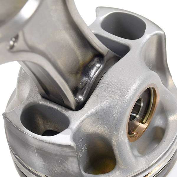
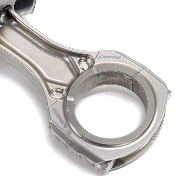
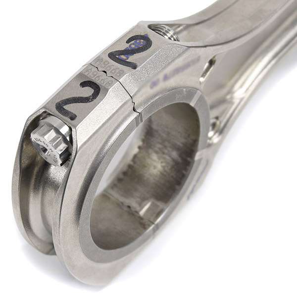
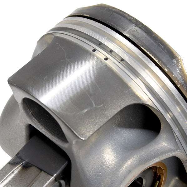
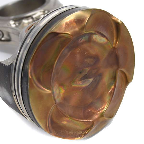
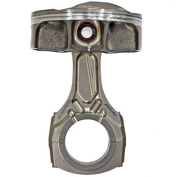
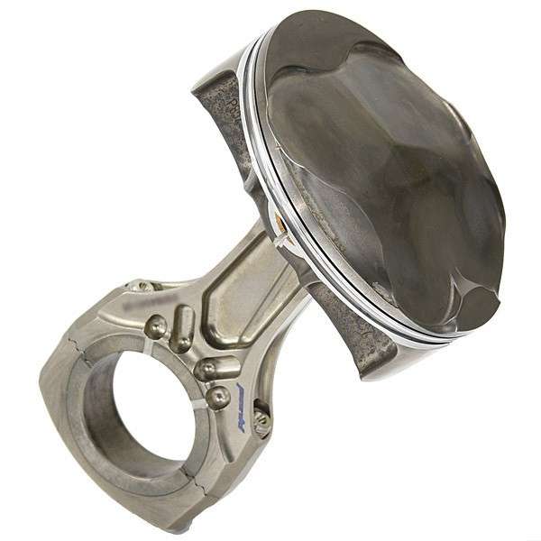
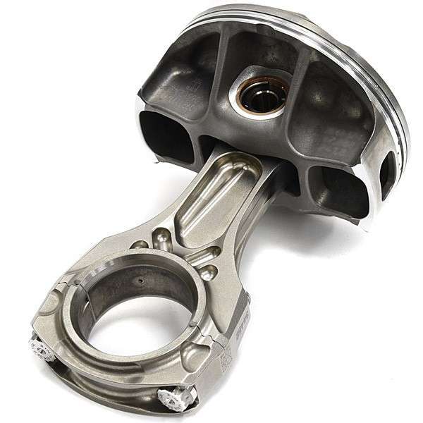
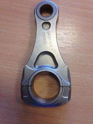
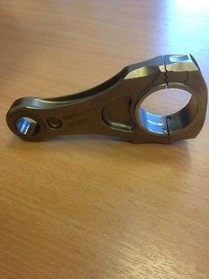
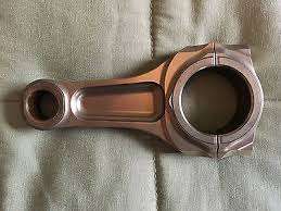
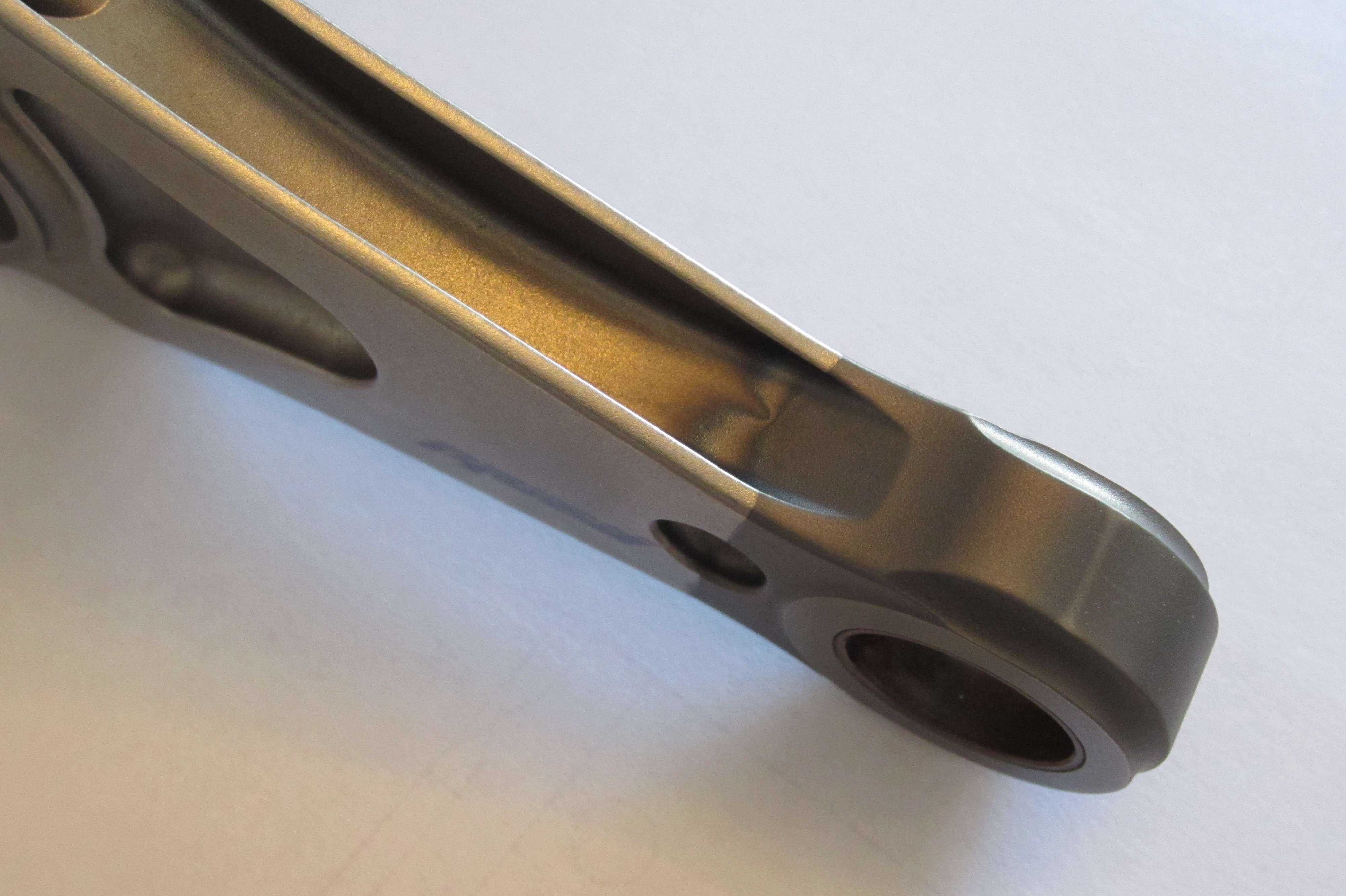
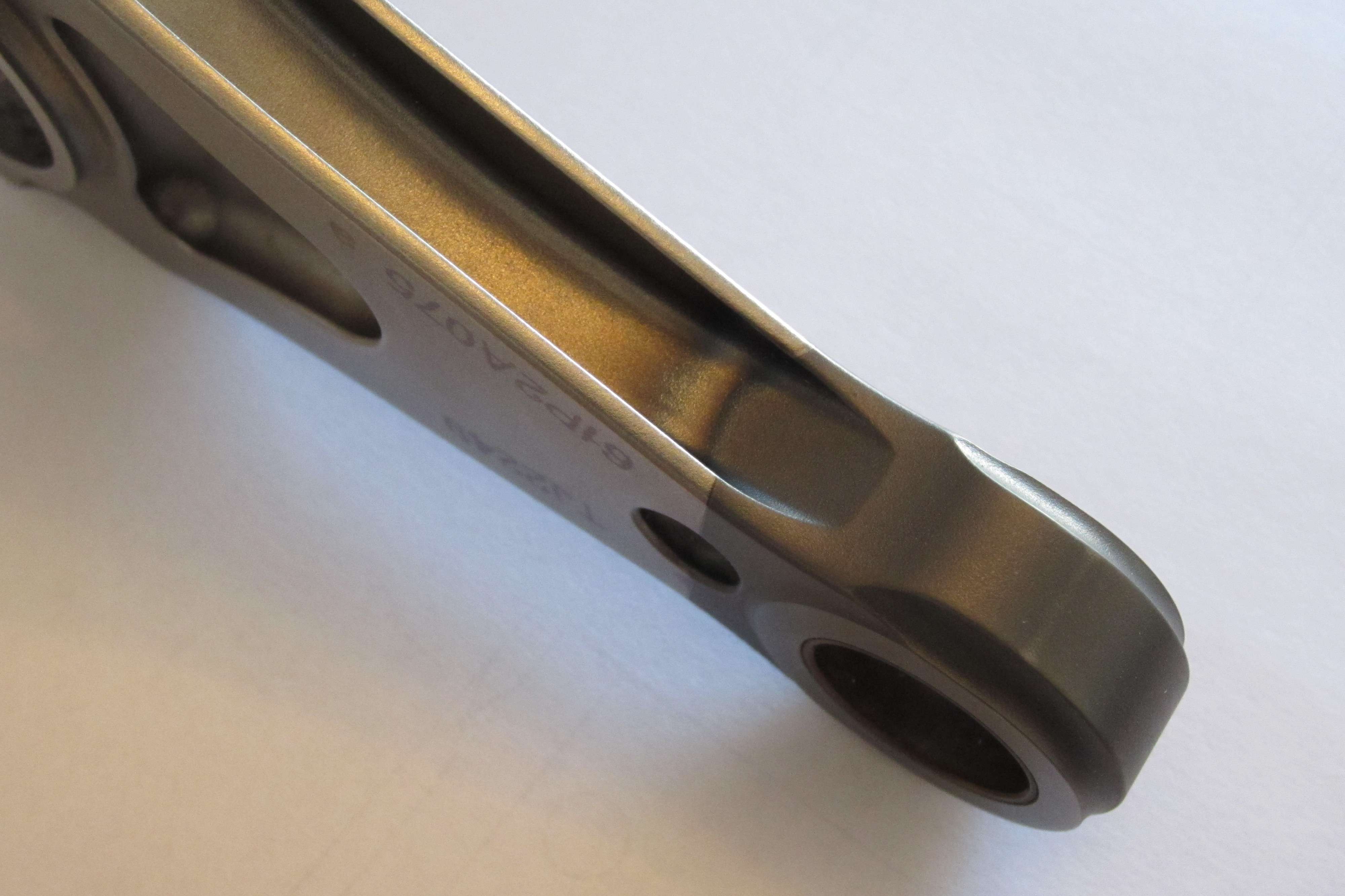
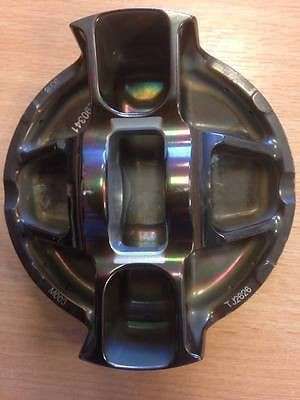
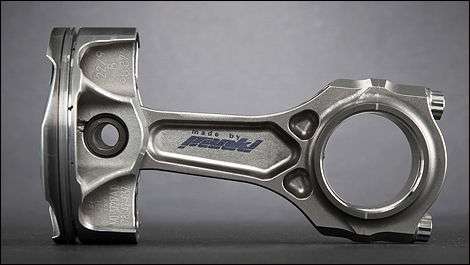
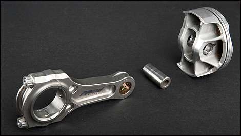
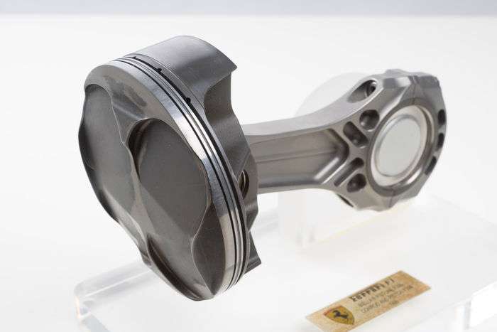
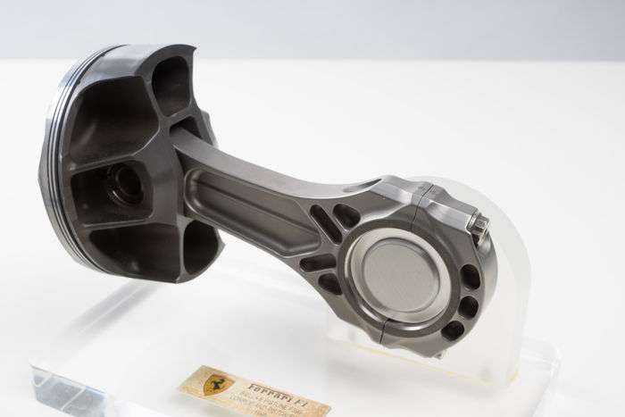
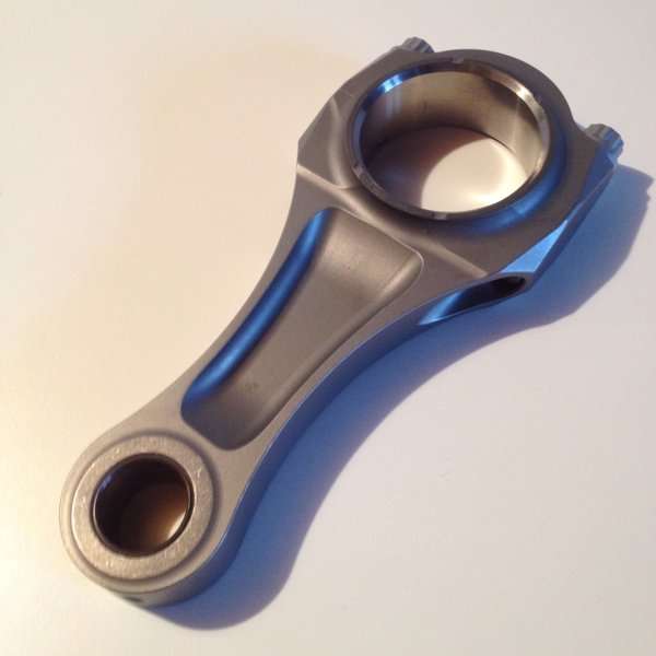
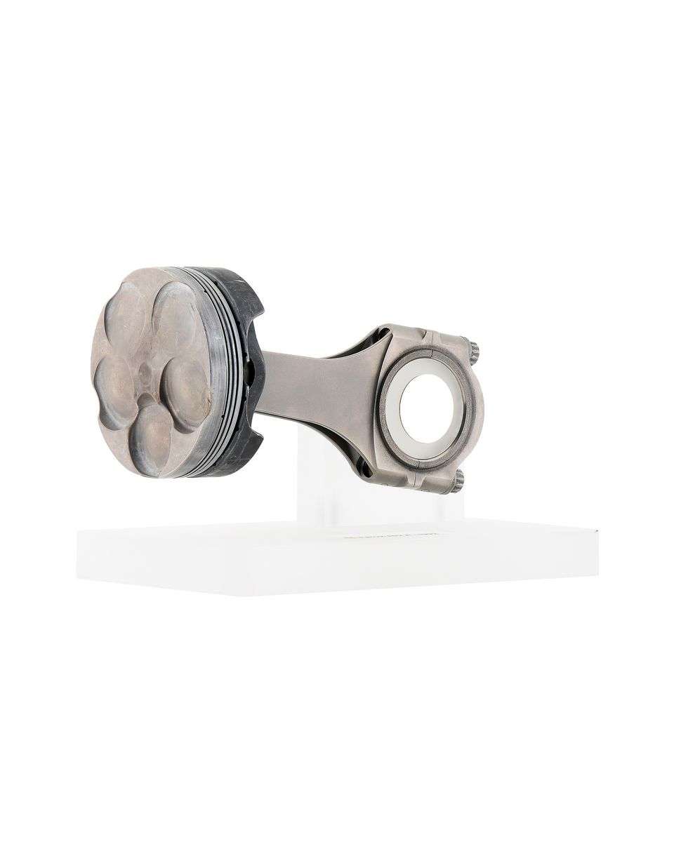
For reasons I can't explain I am really fascinated by F1 conrods. I run a Google search every few days with "F1 conrod" and look through the images to see what pops up. Yesterday was a BIG surprise when a current gen 1.6L V6 Ferrari rod and piston showed up at a Japanese collector site (www.italiazakka.co.jp/shop/20949-0-en.html) (All images are used without permission. If you want something removed please contact me and I will take it down.):
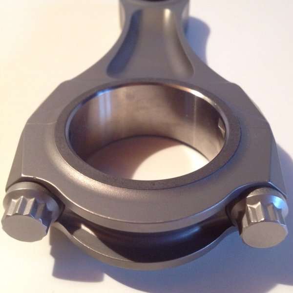
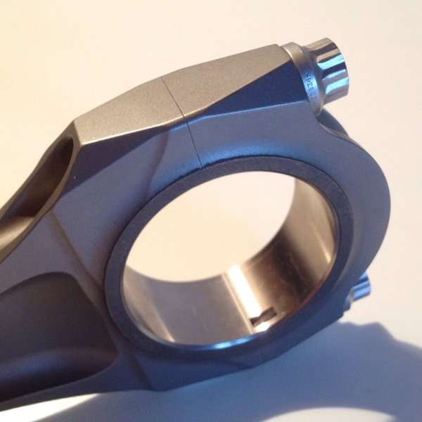
2014 - present, turbocharged 1.6L V6:
2006 - 2013, normally aspirated 2.4L V8:
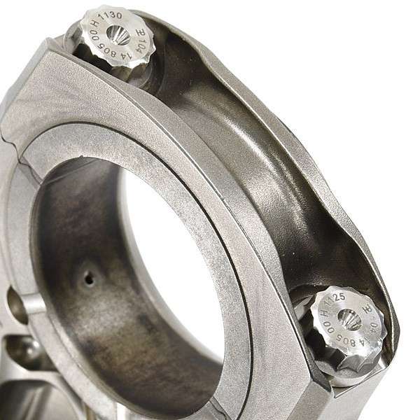
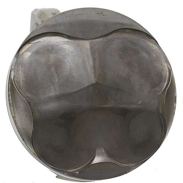
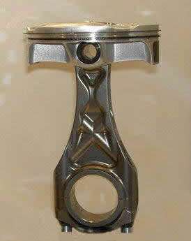
Ferrari V8, no date given: These resemble the last of their V10 rods quite a bit, but the caps have the more 'modern' serrated locating feature. The piston is also different: Check out the windowed skirt in the sixth image. I don't recall ever having seen that feature before.
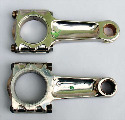
Cosworth V8. Bottom version must have come first:
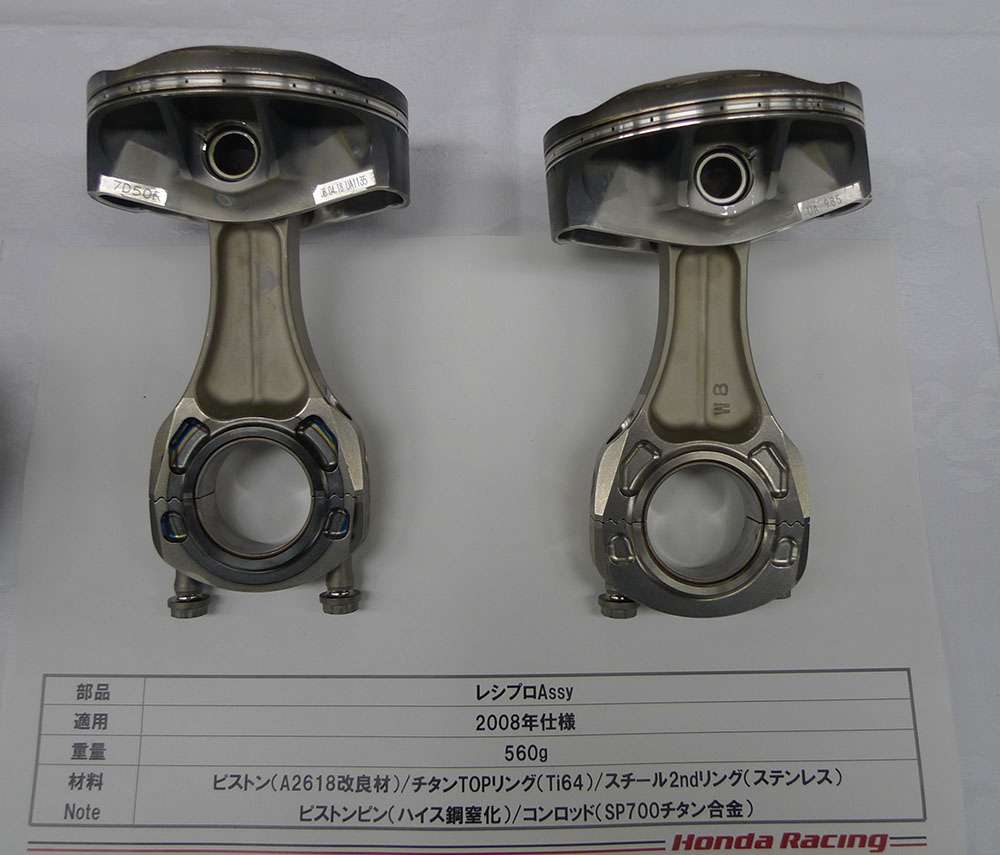
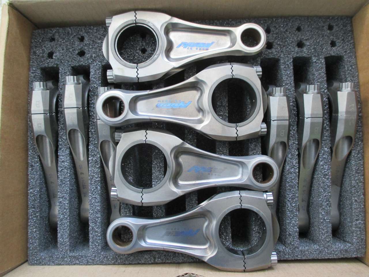
Honda V8, which never raced? Interesting that these are all labelled 6/4 Ti and not the more exotic powder metallurgy Ti used later (Sorry, can't remember the full name.). Note that the big end on the left rod below seems to have the same mystery surface treatment that the 1.6L rod and the later Cosworth V10 rods have on their small ends...
2000 - 2005, normally aspirated 3.0L V10:
Peugot V10: The first two images MUST be the older design. The rods in the third image are surprisingly different than the Cosworth V10 versions shown below.
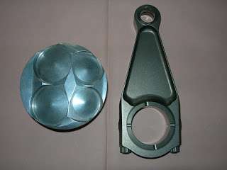
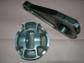
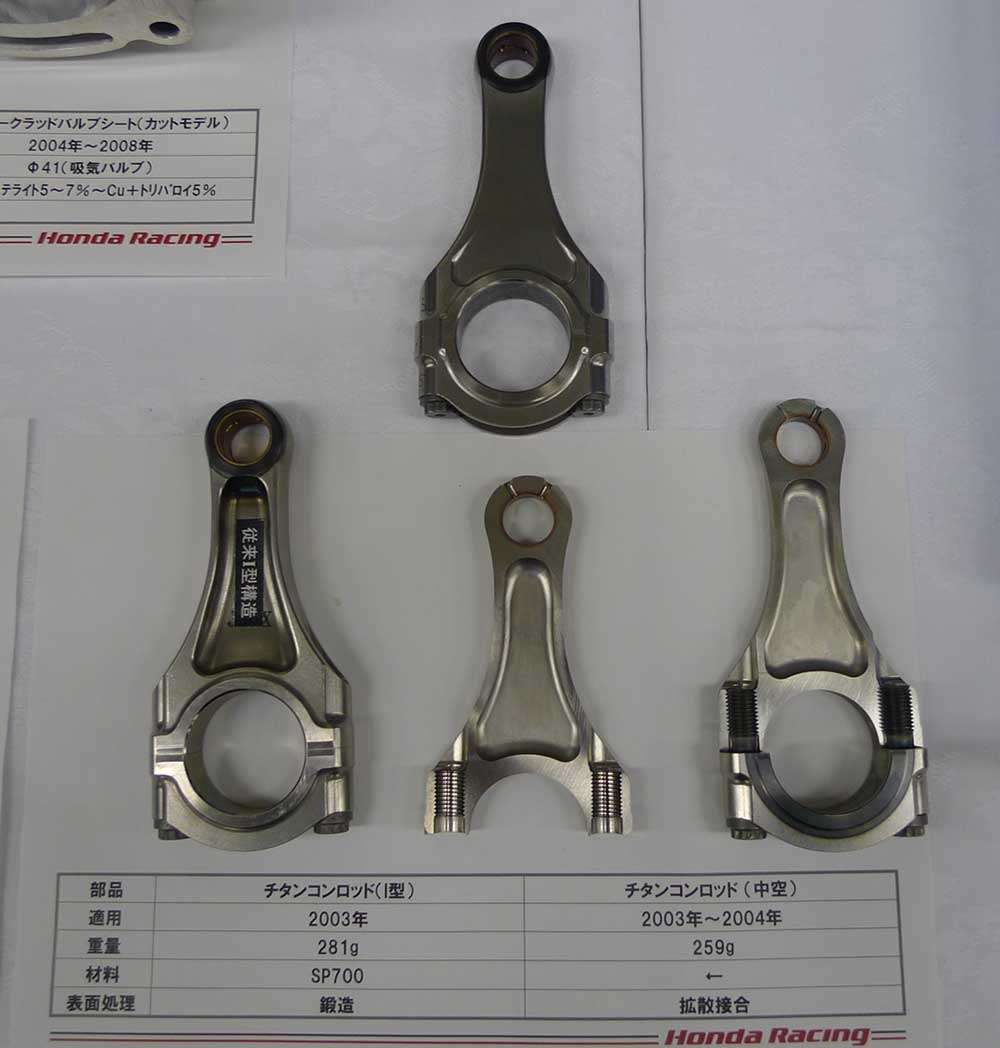
Honda V10: Nice research paper on the hollow rod effort here: http://www.f1-forecast.com/pdf/F1-Files ... P2_34e.pdf I don't think the hollow rods ever raced.
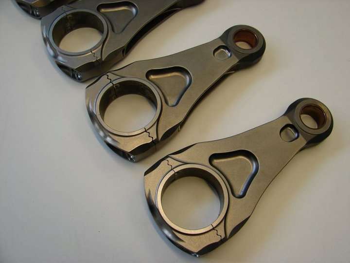
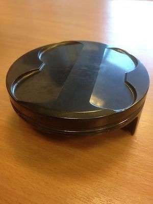
Cosworth TJ N.A. V10: The differences shown being either different vintages or different badged teams. This thread goes deep on the Cosworth TJ rod: viewtopic.php?f=4&t=9346&hilit=Pankl+Conrod. Note the difference in how the caps are machined, and how they are located. The piston is just to have something to compare to the 1.6L version above (I don't think anyone raced a full 'dlc' coated piston, so this seems like an experiment.).
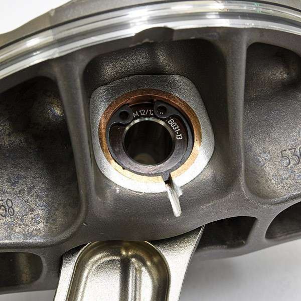
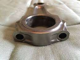
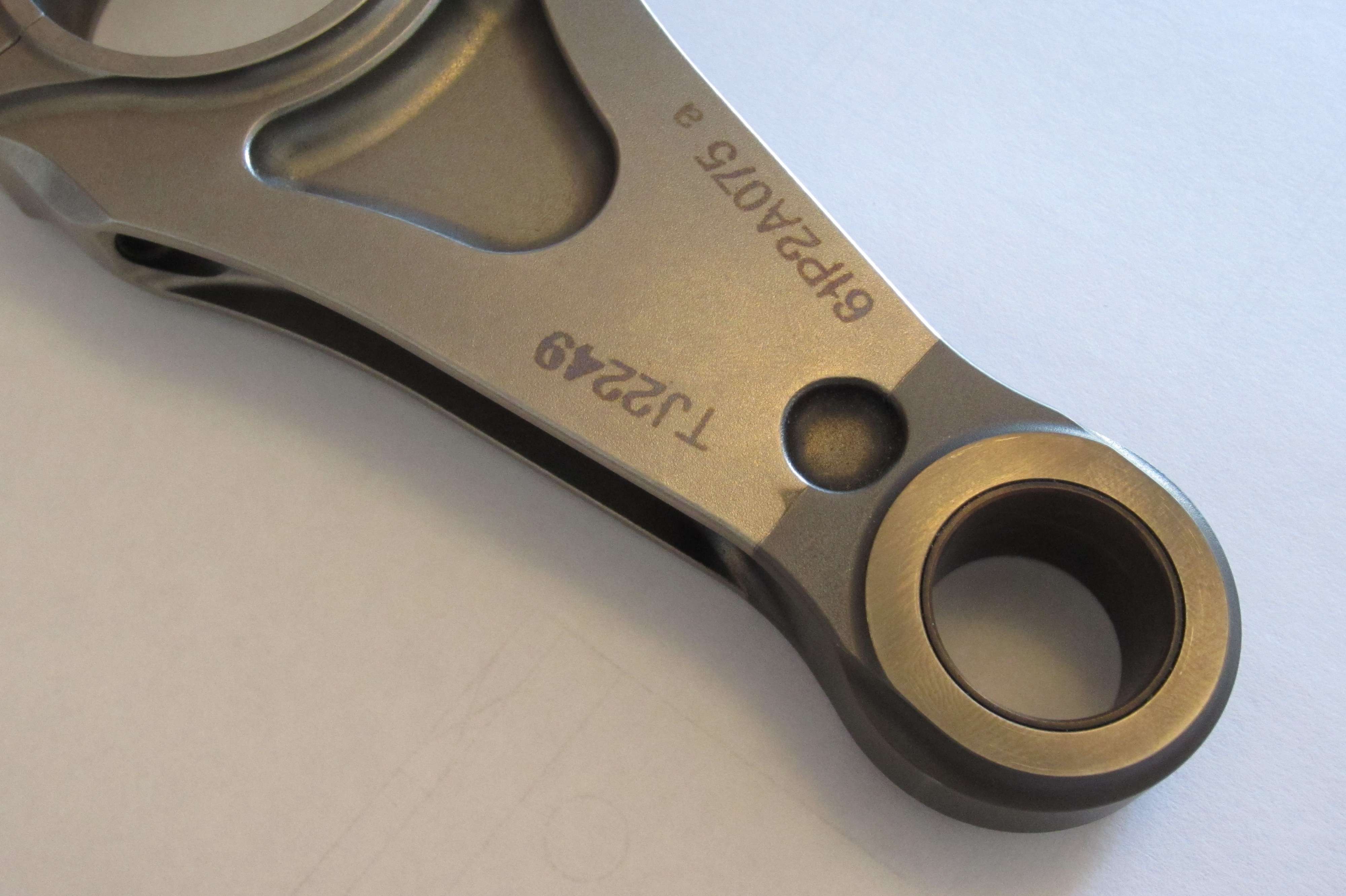
Here are some better images of the surface treatment applied to the small-end, presumably to eliminate galling when pressing the bushing in.
Ferrari F-399 V10 (1999): Not sure which version came first. Top version could be a cousin to the V6 rod above. These and the Honda rods are the only forced pin oiling examples:
Ferrari F1-2000, N.A. 3.0L V10:
Ferrari F-2003 V10:
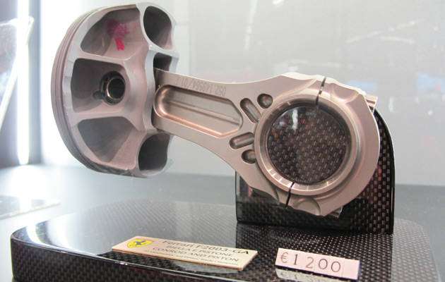
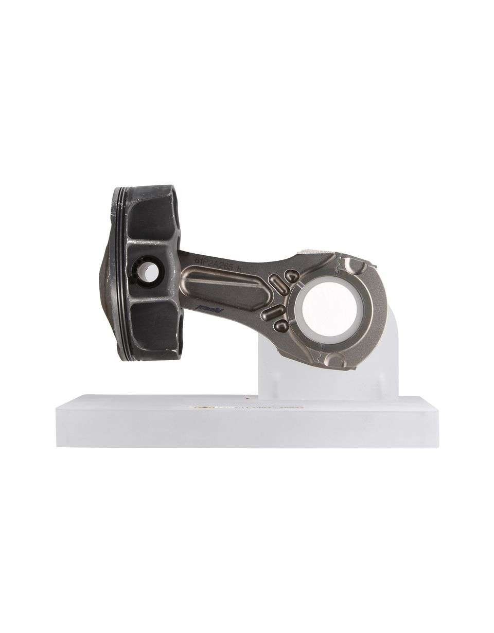
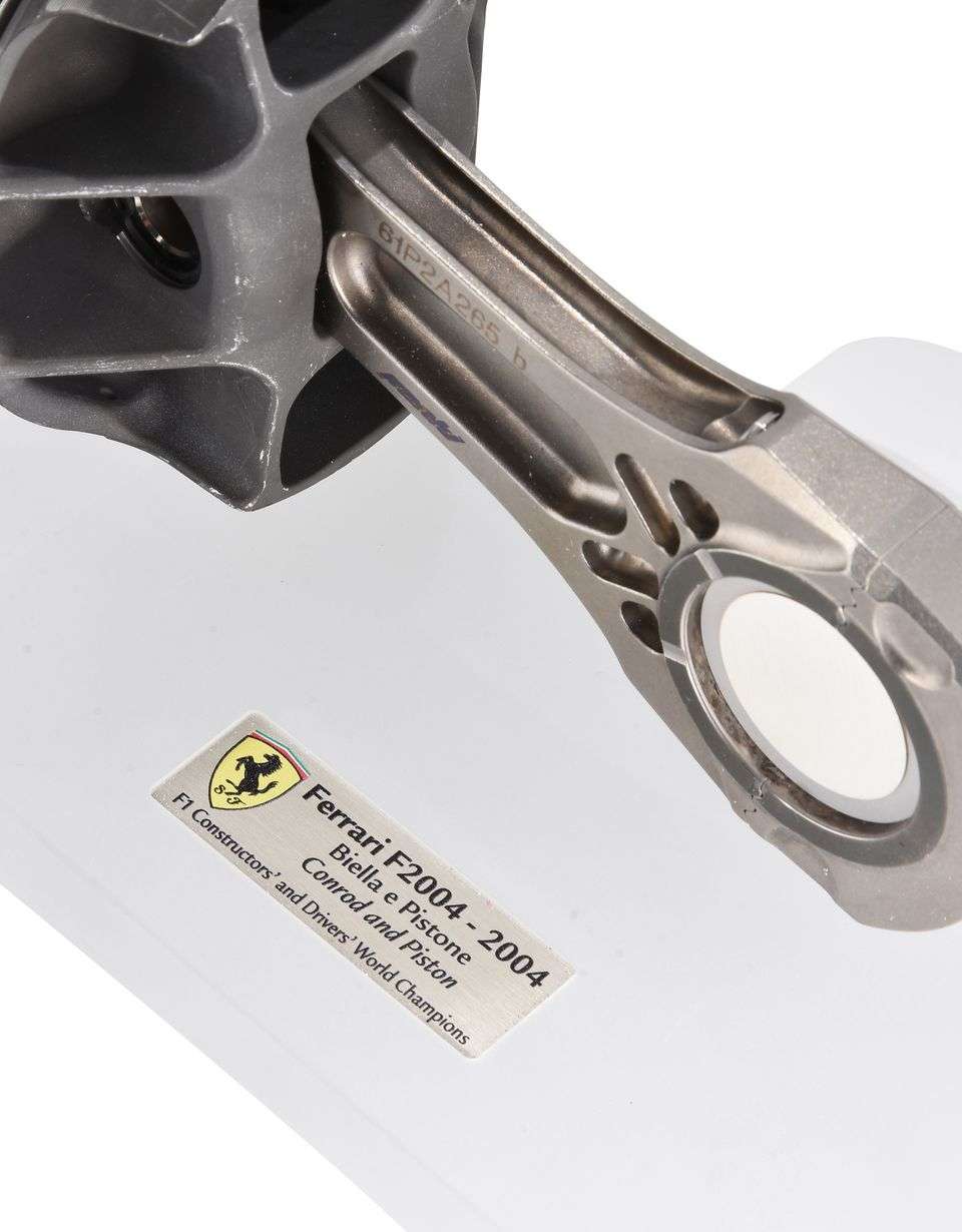
Ferrari F-2004 V10: Is the angled small end oiling about timing? This also seems like the first 'hybrid' geometry Pankl rod, part "I Beam" part "H Section":
1986 - 2000, 1.5L Turbos, 3.0 L N.A., 3.5 L N.A.:
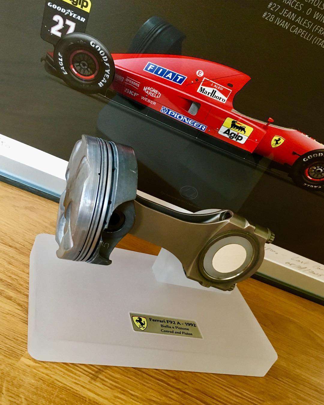
1992 Ferrari F92A, N.A. 3.5L V12: These look like steel.
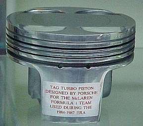
1984 - 1987 1.5L Turbo V6
TAG - Porsche: At the end of its development it was hitting 1,060 hp in quali mode, @ 12,600 rpm. Piston included for comparison to the current gen.
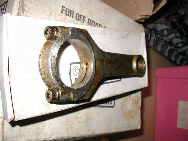
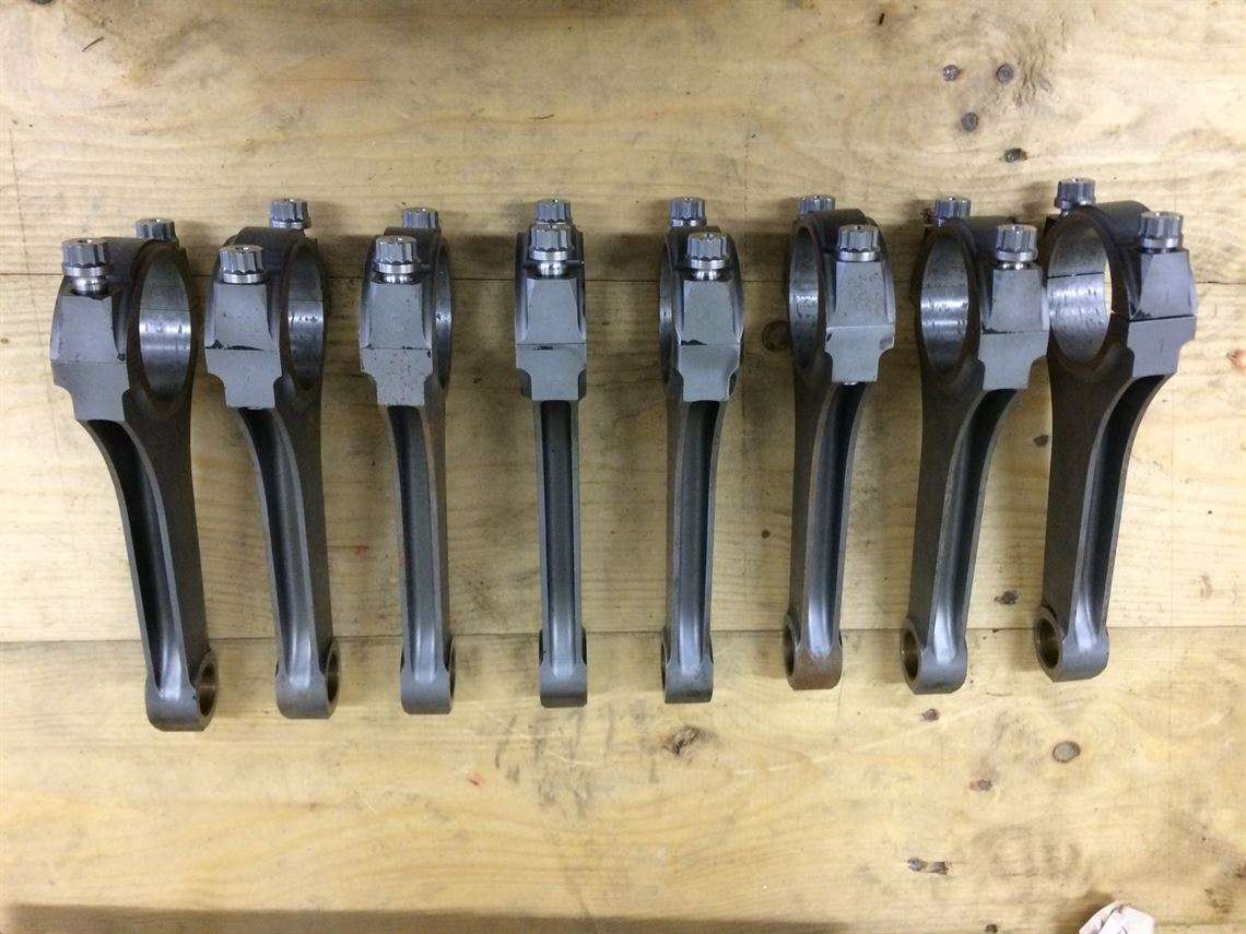
1967 - 1985, normally aspirated V8:
Cosworth DFV / DFR V8: These are steel. Note the 'balance' pad at the small end, just like most stock rods...
Orphans: I can't link these to a year or car. Any info here greatly appreciated.
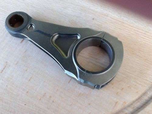
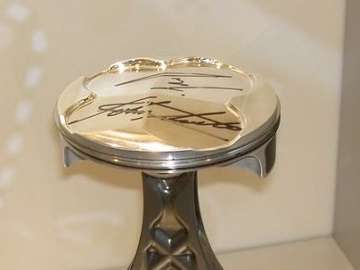
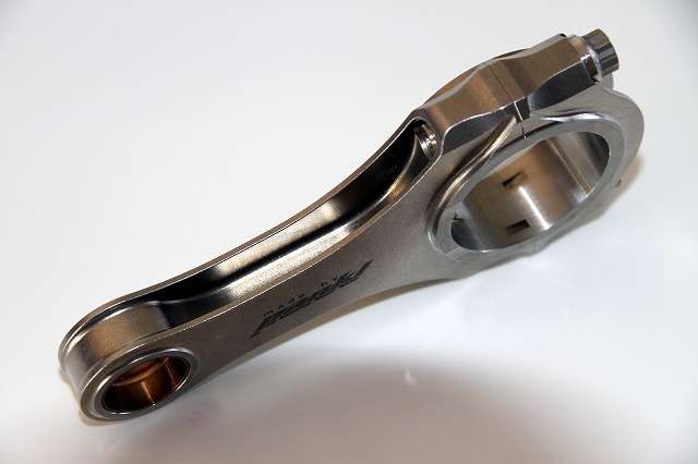
Pankl "Mystery Rod #1": I thought this was just a 'demo' piece, but the autograph on the piston makes me think it was 'real'. Lack of serrated cap location says 2005 or earlier vintage.

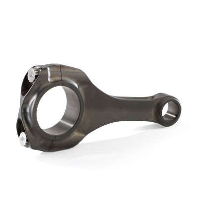
Pankl "Mystery Rod #2": This one only shows up in their annual report. It may not be 'real'. The organic shape is sure a contrast to Mystery #1 above. Again, the lack of serrated cap location says 2005 or earlier vintage.
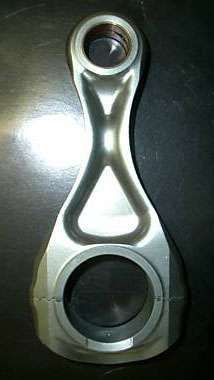
Pankl "Mystery Rod #3": This is also something from their annual report and again may not be 'real'. Interesting form though. Ditto for the lack of serrated cap location saying 2005 or earlier vintage.
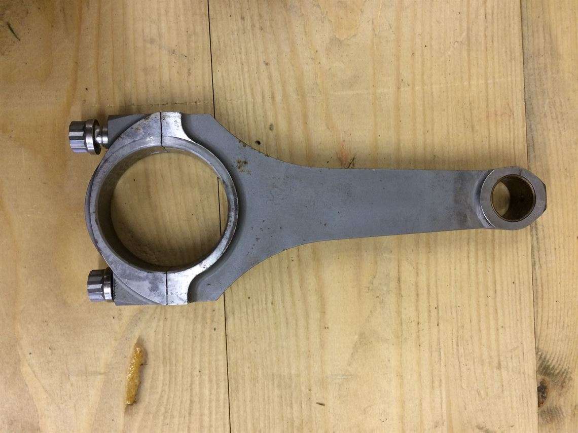
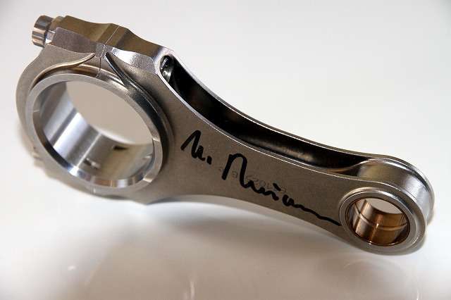
Pankl "Mystery Rod #4": This was on a Japanese collector site and is supposedly a BMW F1 piece, autographed by Dr. Mario Thiesen (spelling?). These look like steel to me. Again, the lack of serrated cap location says 2005 or earlier.
Lastly, for a laugh: Although I am clearly a Pankl fanboy, this is not me...
Please chime in with insights and commentary. If you have more images please do share. I didn't intend for this to be a Pankl-fest, so please share other manufacturers if you have info.
Cheers,
Jon