F1 Hydraulic Oil Heat Exchanger, a closer look

All that has to do with the power train, gearbox, clutch, fuels and lubricants, etc. Generally the mechanical side of Formula One.
Brian.G
Brian.G
334
Joined: 10 Dec 2010, 23:52
Location: Ireland

F1 Hydraulic Oil Heat Exchanger, a closer look

Post

Another part under the spot light, this time the F1 Hydraulic Oil Heat Exchanger and Accumulator,

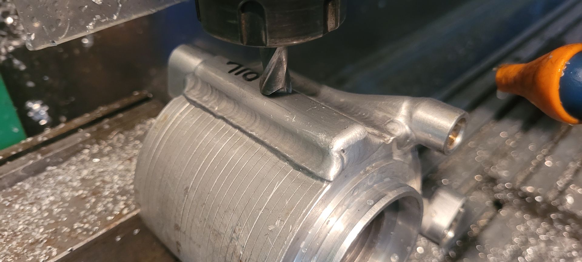
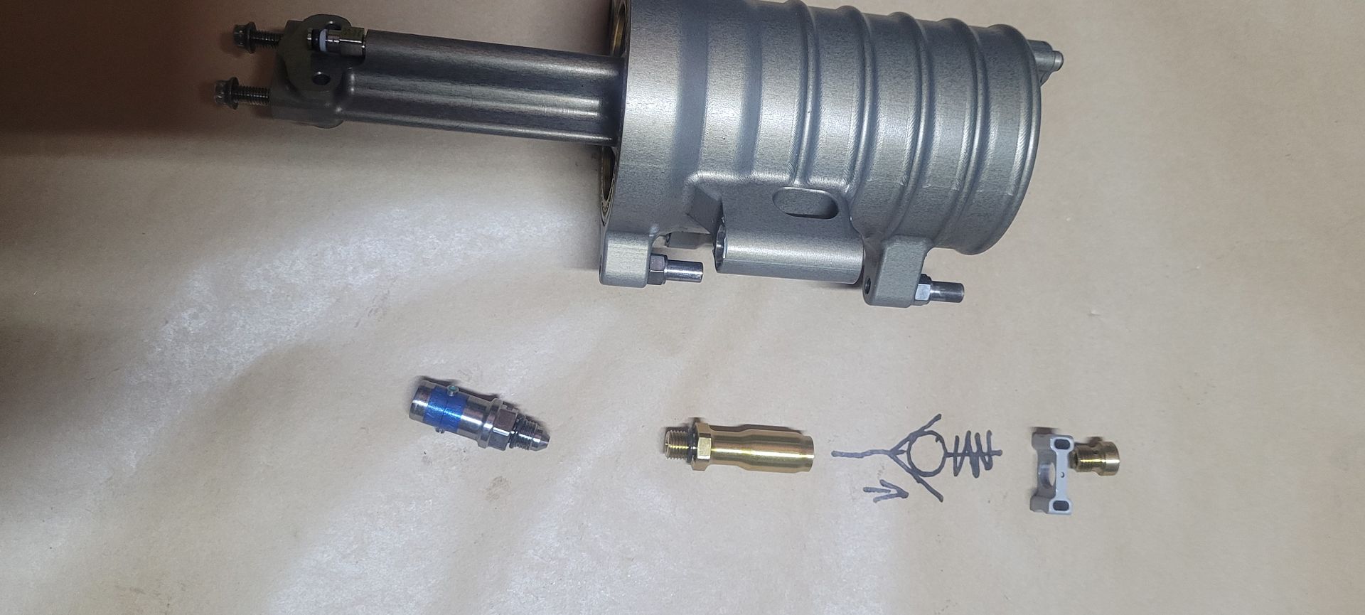
In this thread I will be unlocking a few secrets hidden within this part - The F1 Hydraulic Oil Heat Exchanger and Accumulator, mainly its construction, operation, and some other features.

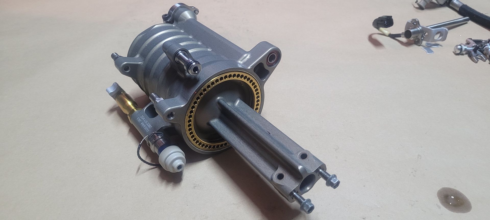
The part in question is from the Williams BMW Fw25 2003. Hard to believe this part is now 20yrs old - it still looks like it was manufactured yesterday. The part was bought blind not fully knowing what it was, the advert had two pictures and it was described as ''Pump''. Initially from the add it roughly resembled a fuel collector combined with the high pressure fuel pump but in the end it turned out it wasn't a pump at all. It is however a hydraulic oil to water heat exchanger with an integrated piston type accumulator.

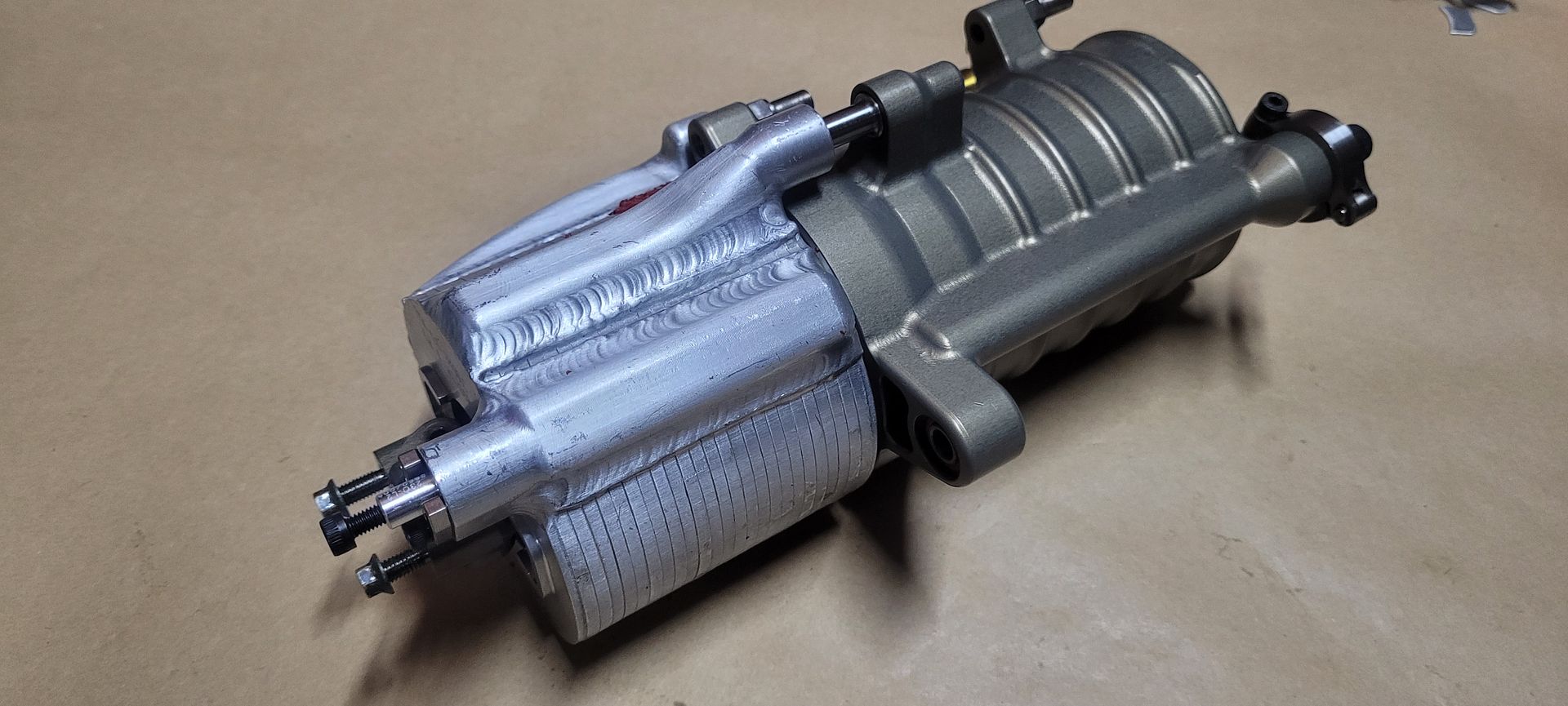
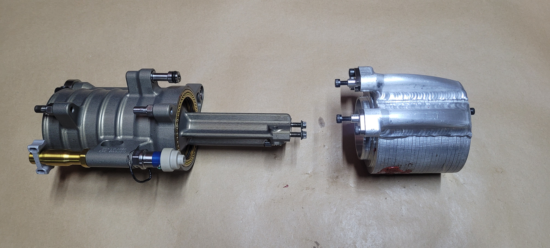
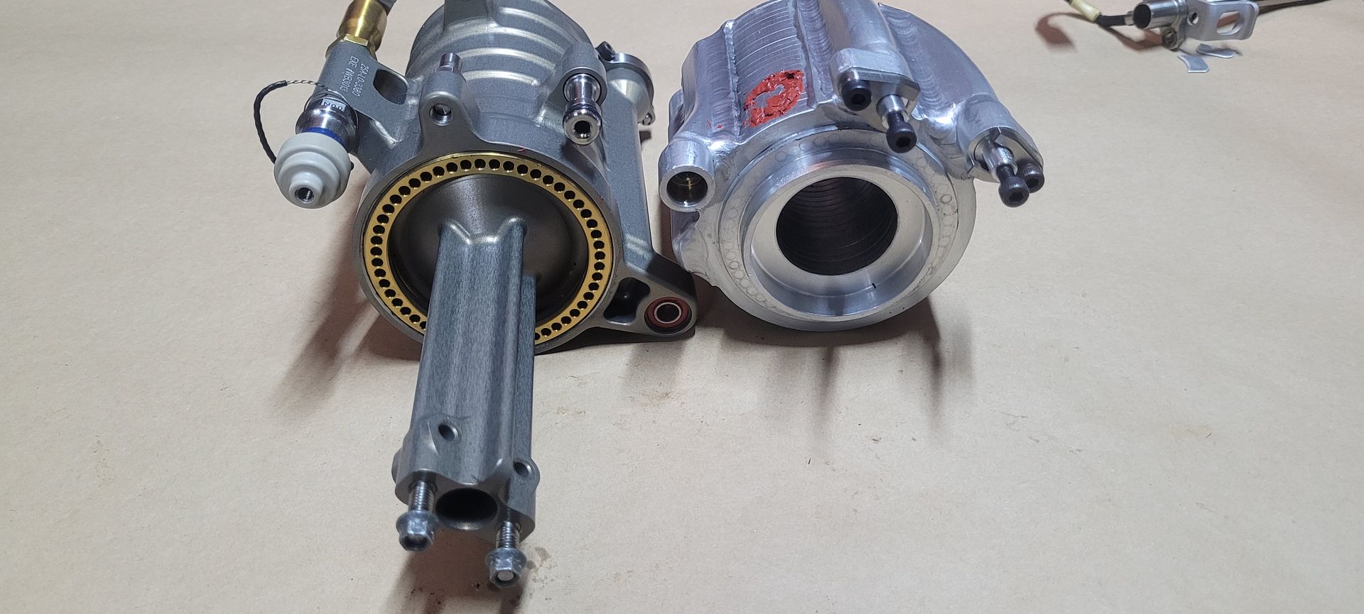
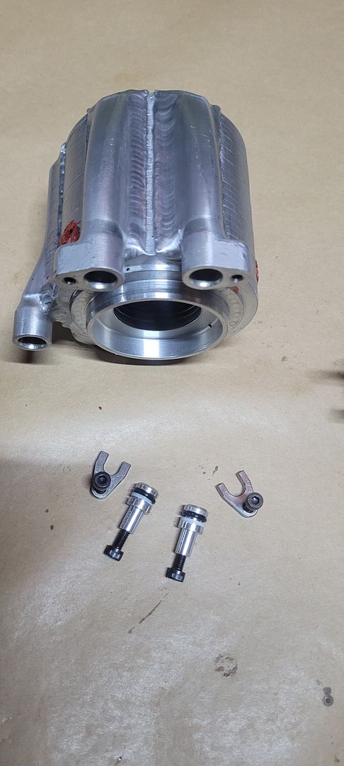
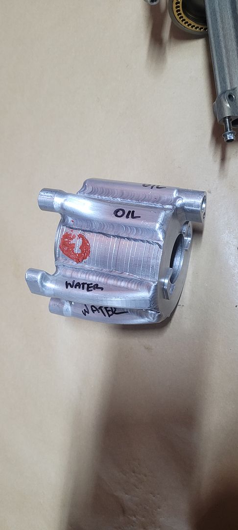
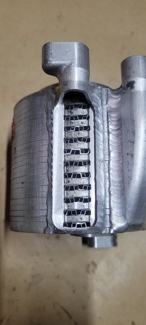
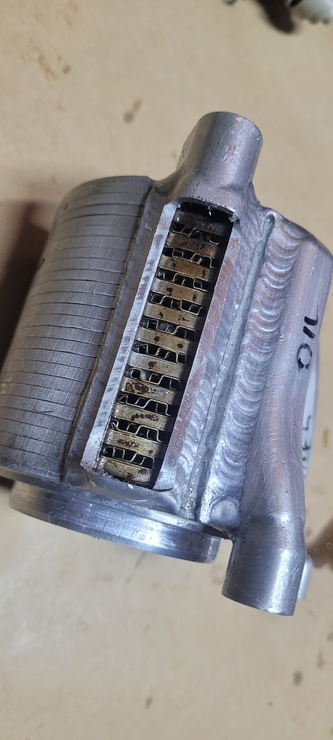
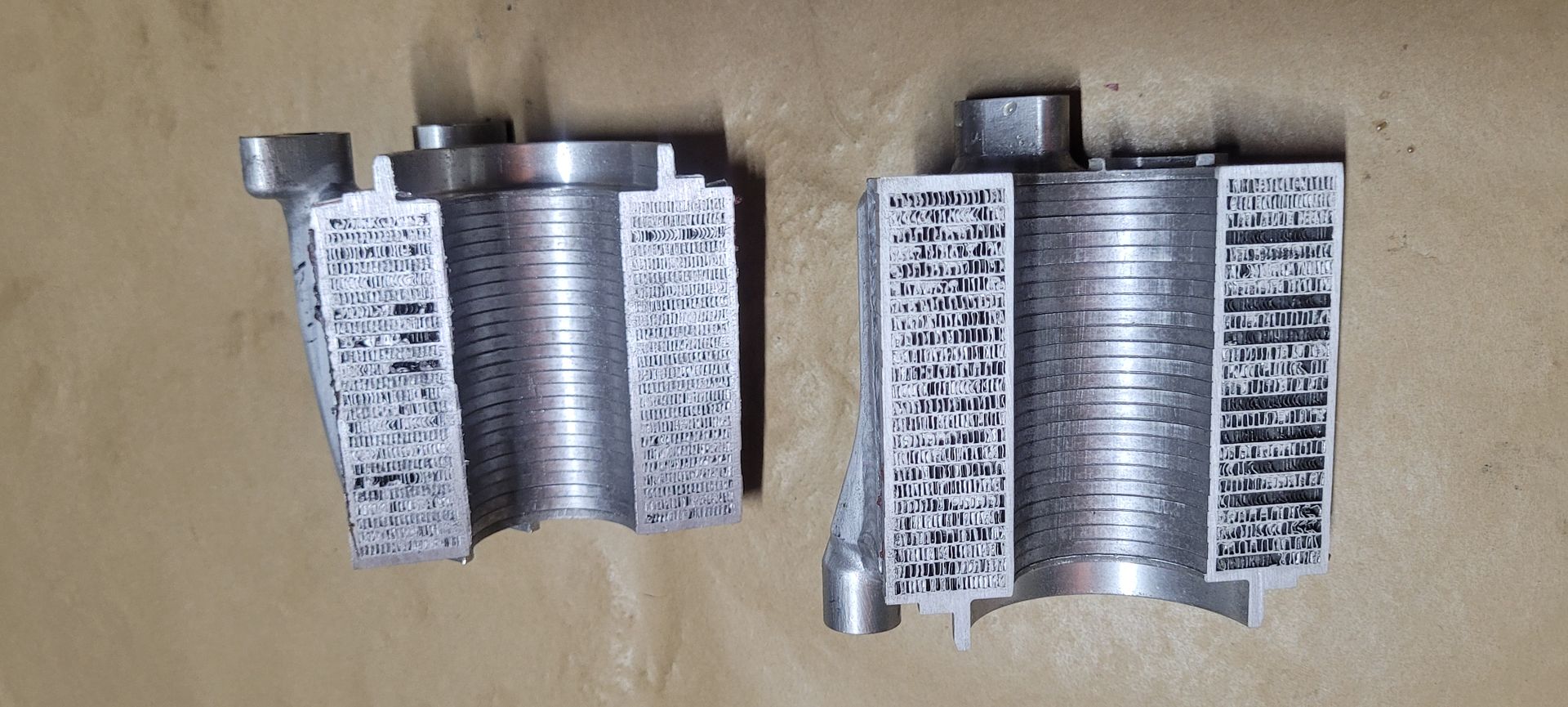
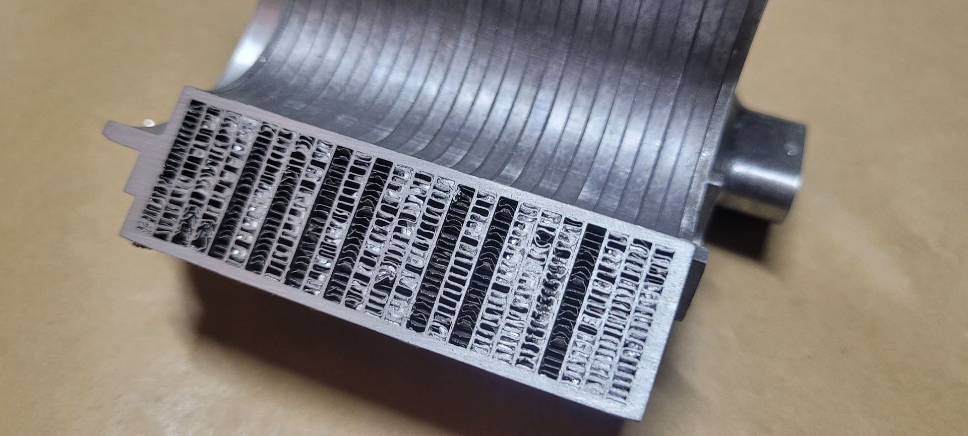
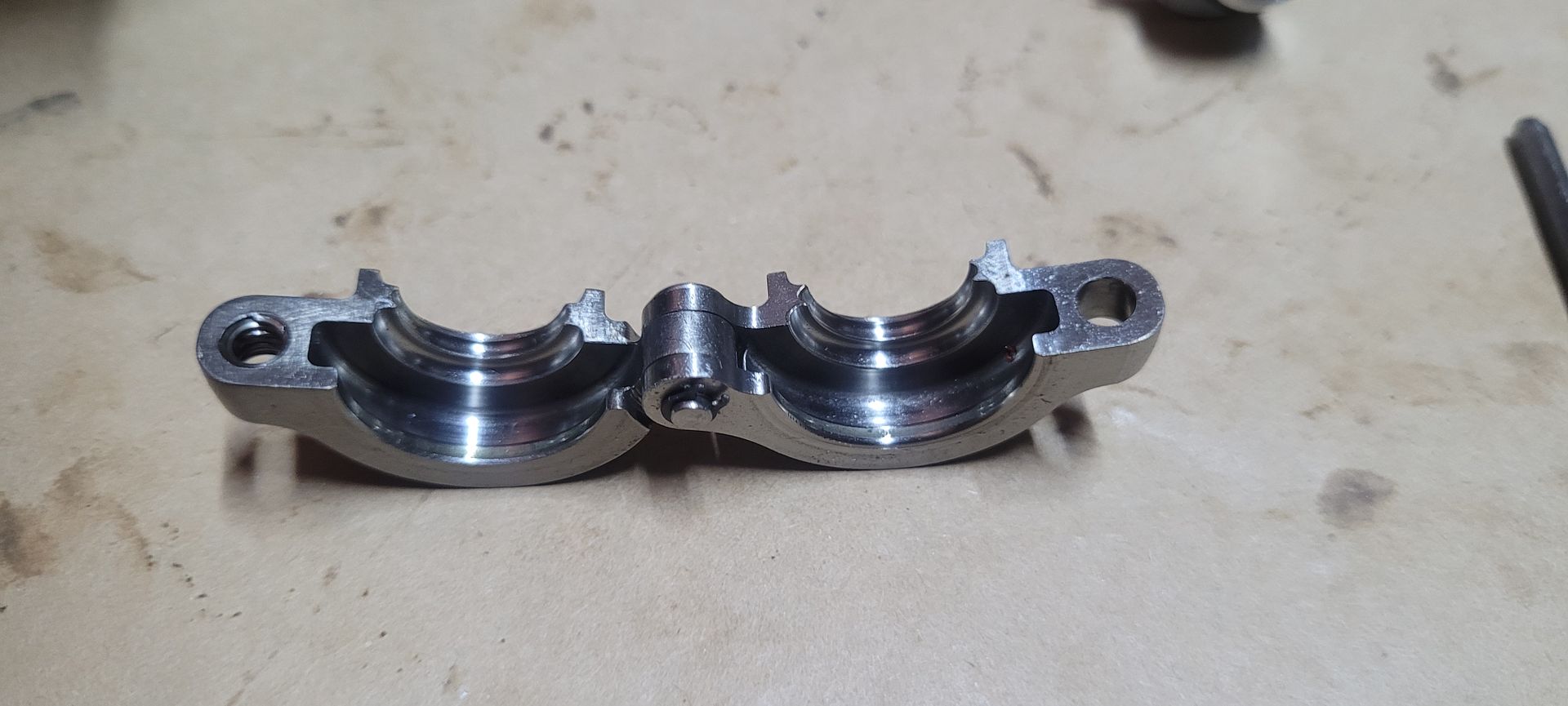
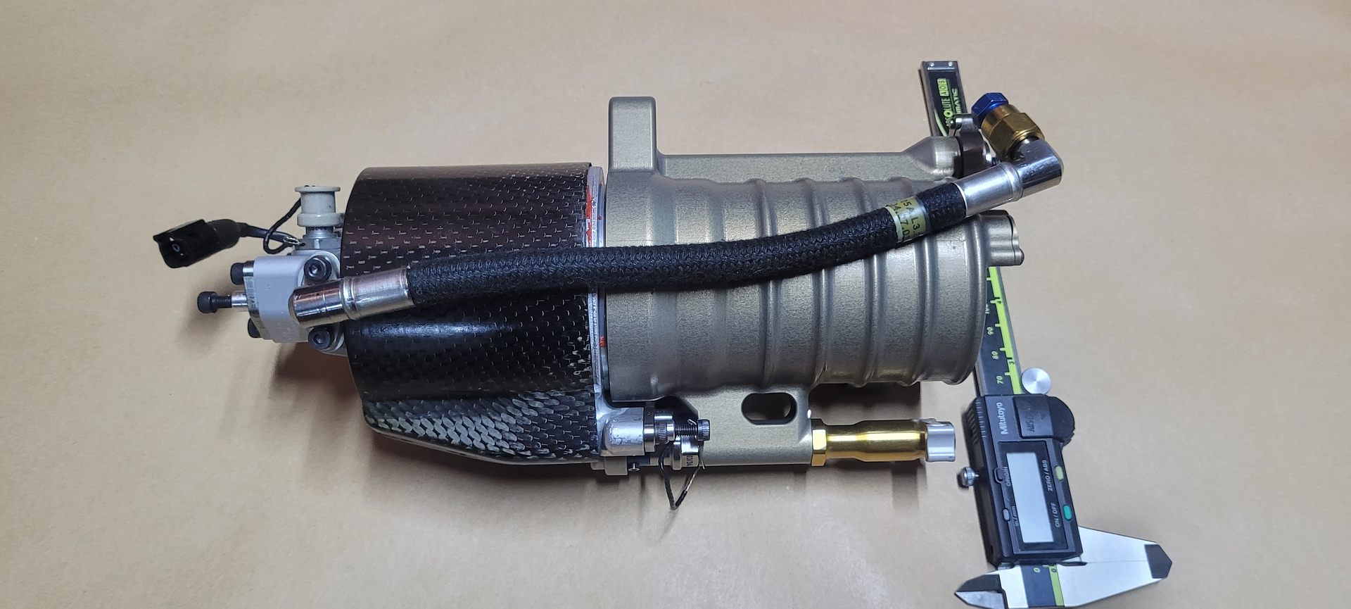
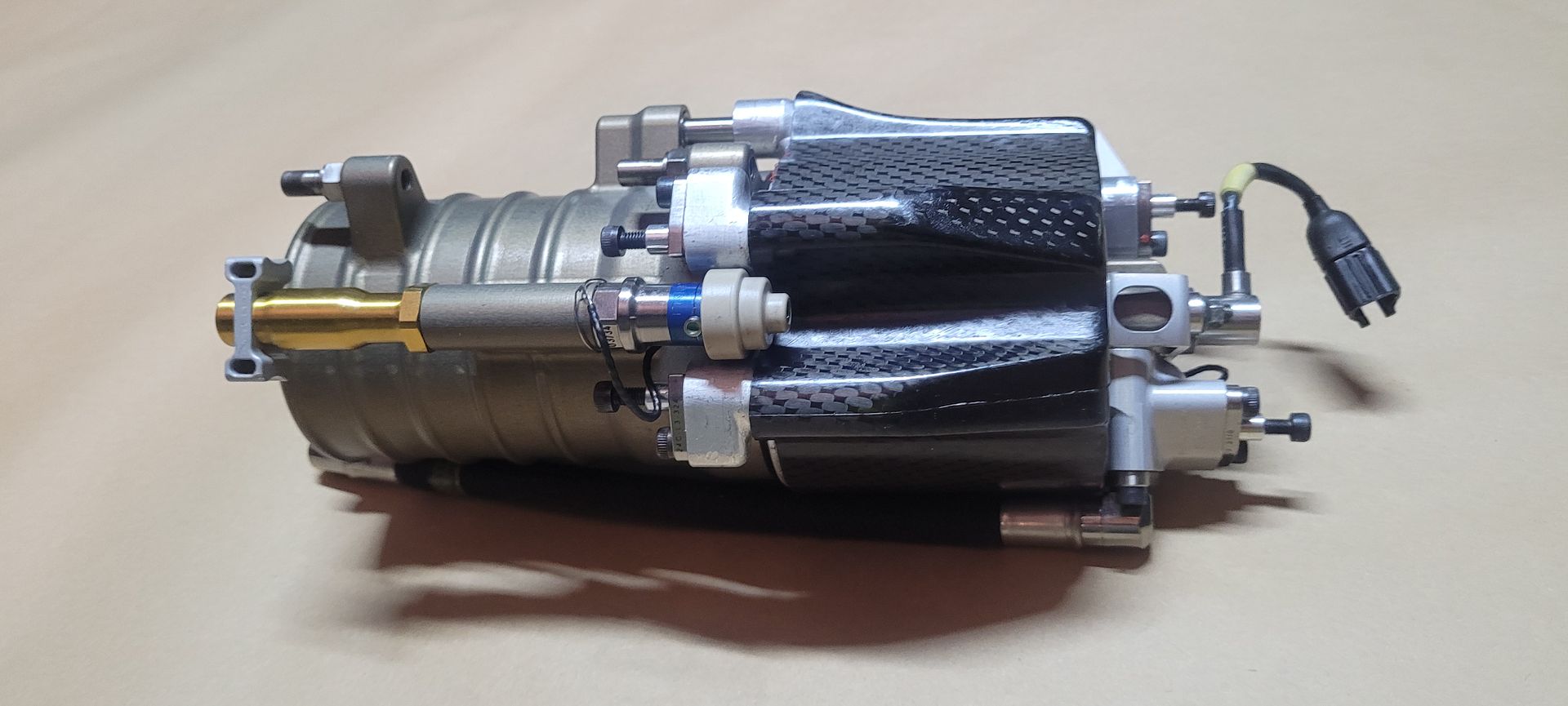
So with that in mind lets push onto the part in hand, it is a beautifully made part as you can see,

Image

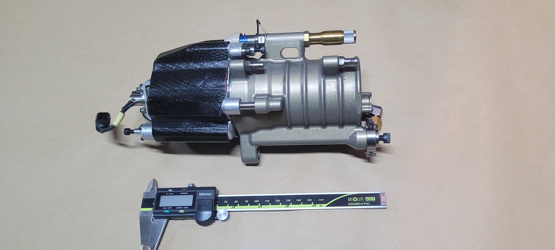
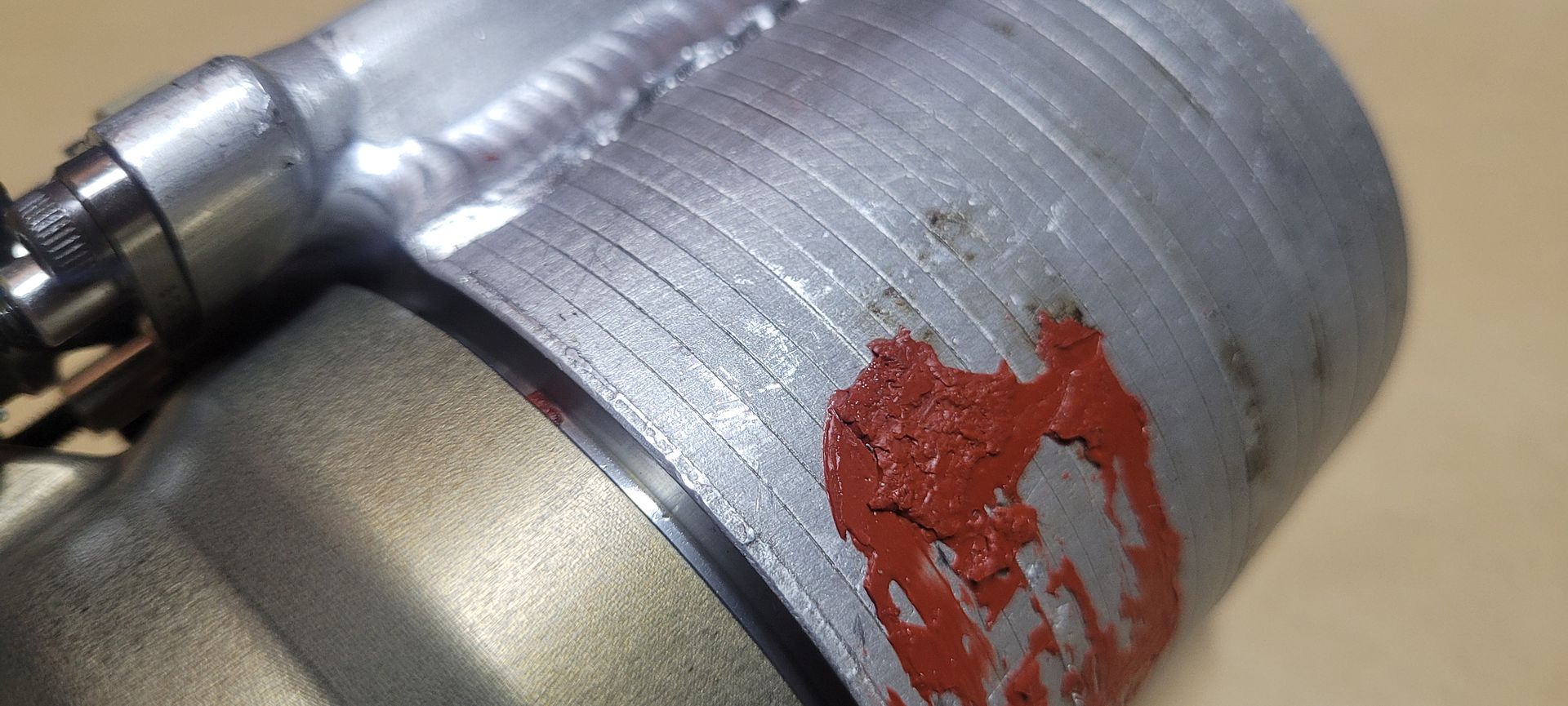
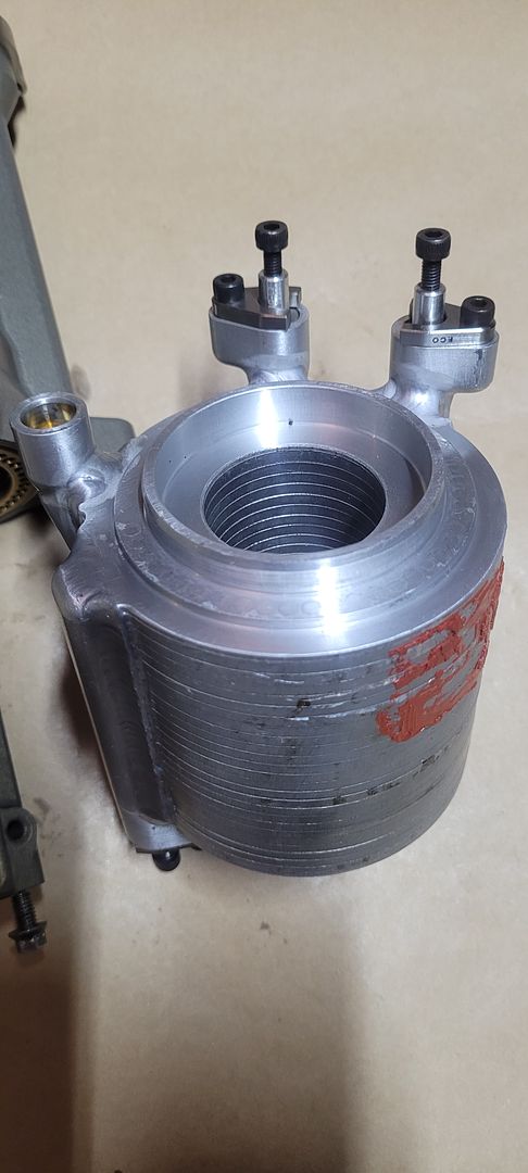
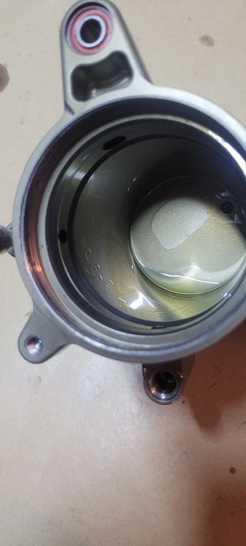
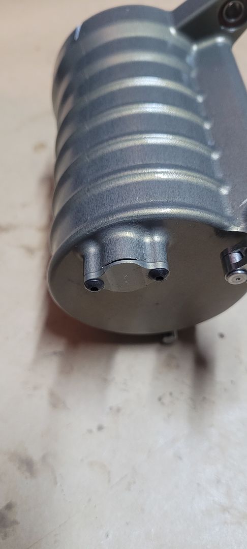
The main body appears to be Type III hard coat anodized 7xxx series aluminium alloy, the outside is left as is post anodizing however the interior bore appears to have been sealed with ptfe and honed - which will be seen later,

Image

Image

Image

Image

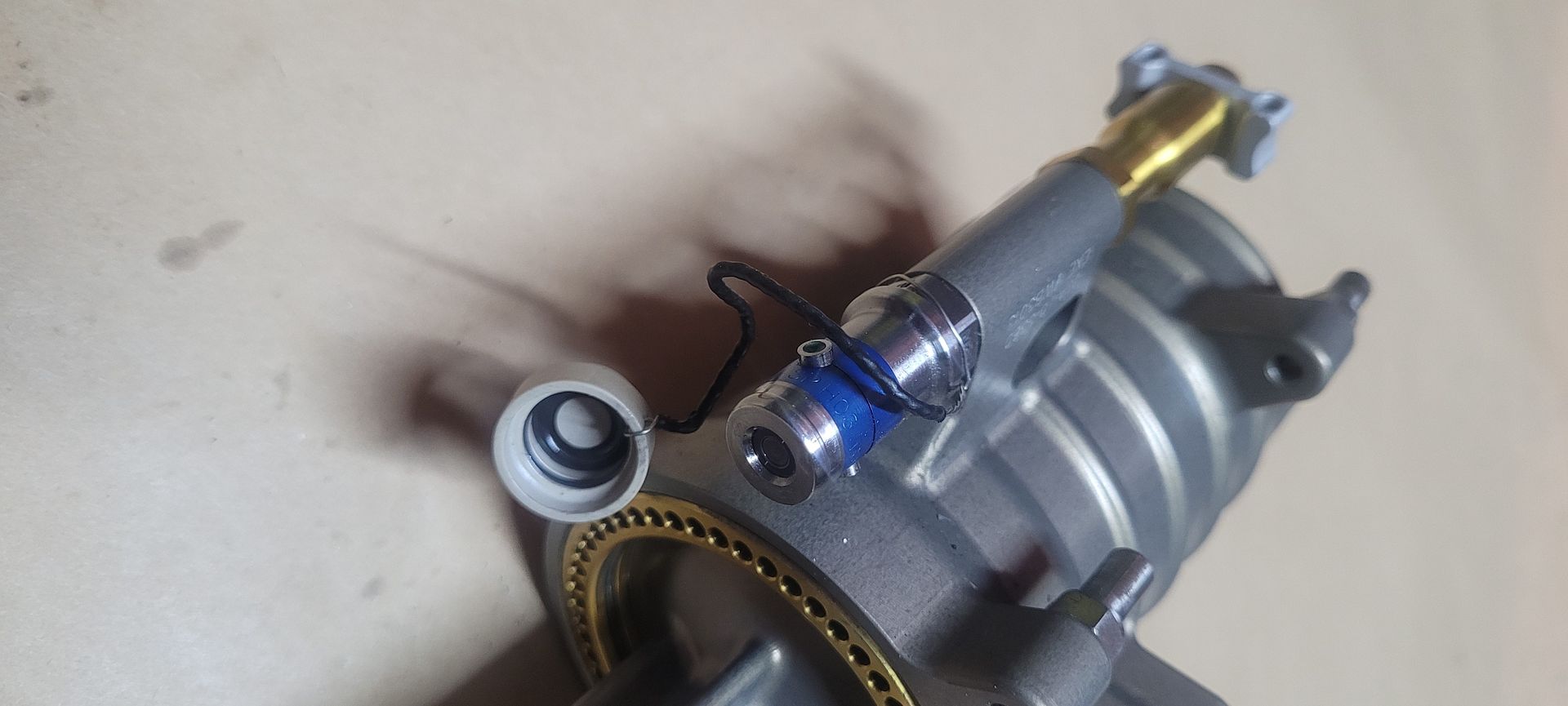
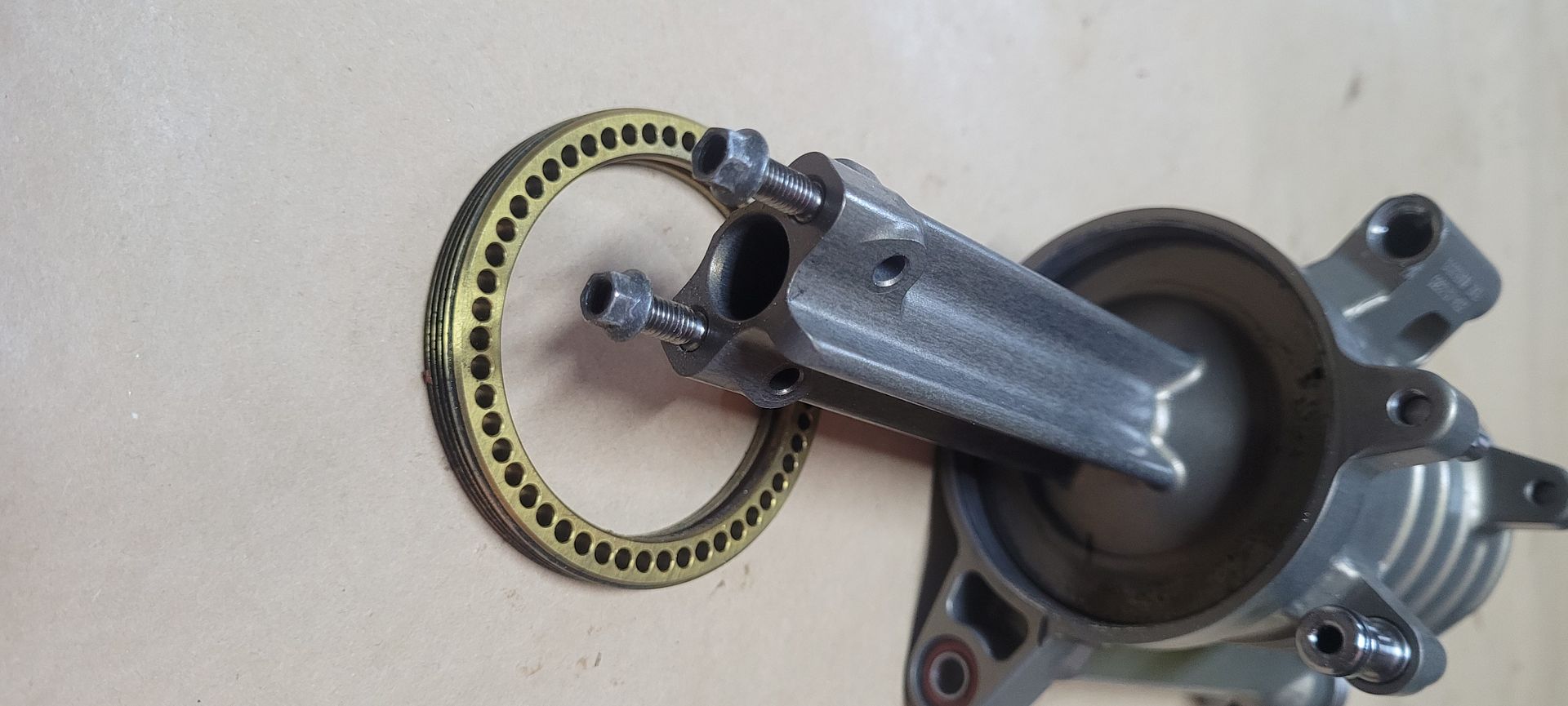
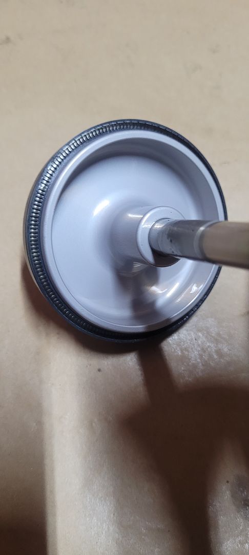
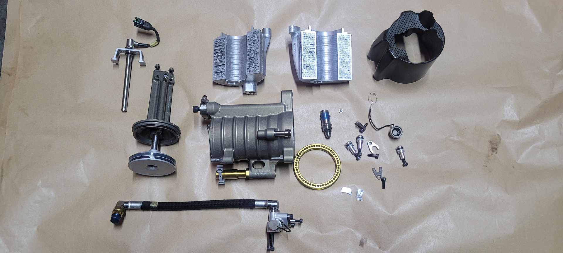
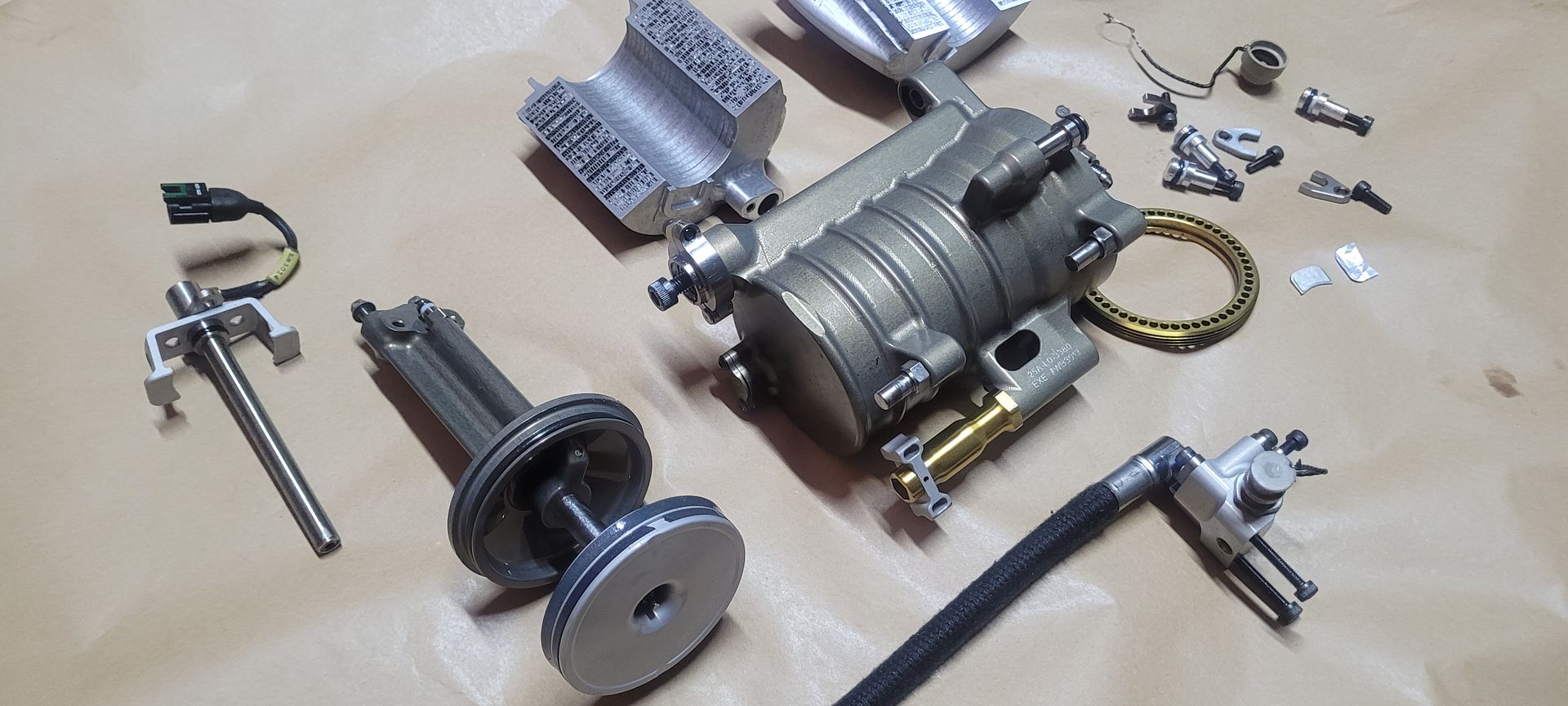
The oil manifold was first removed in order to be able to slide off the carbon fiber cover,

Image

Image

Image

Image

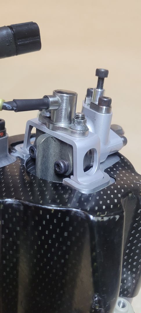
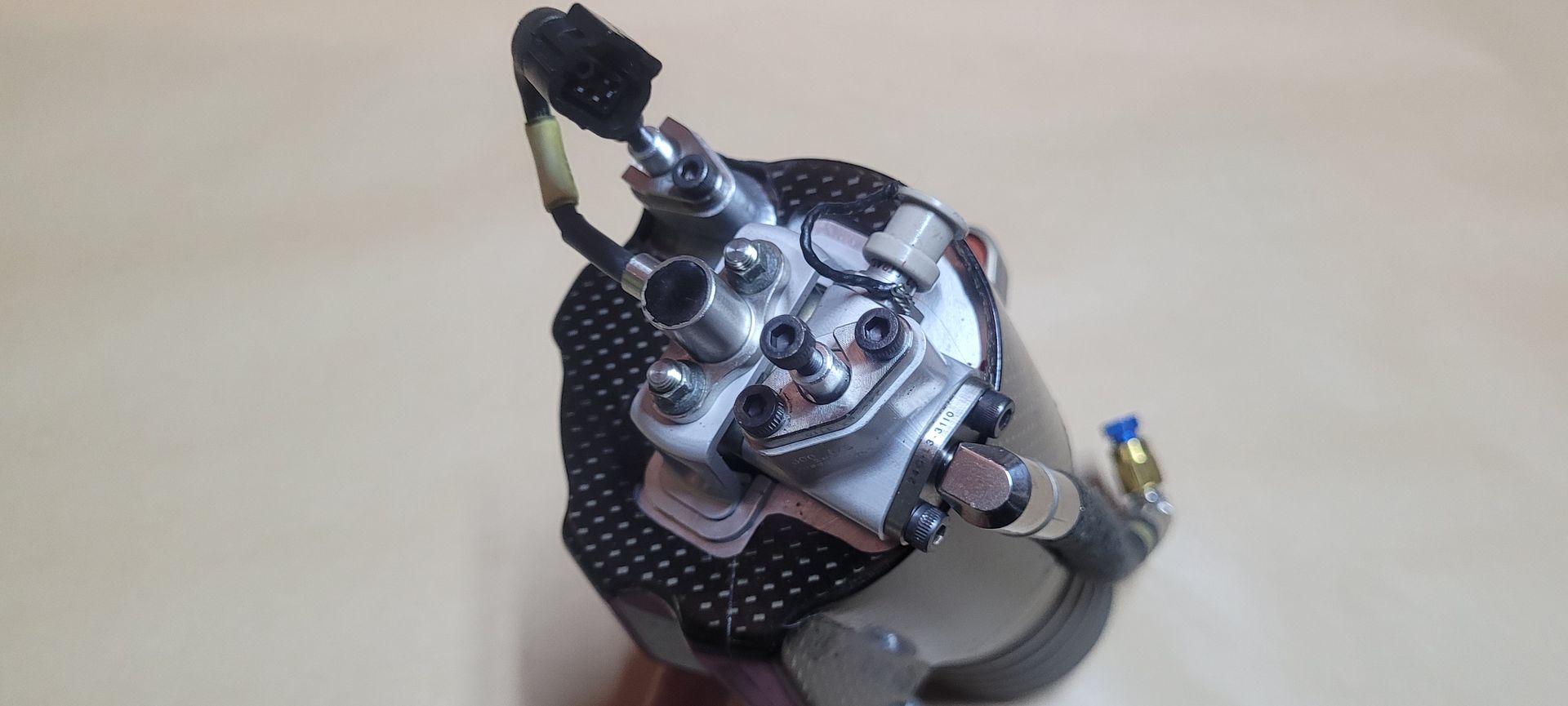
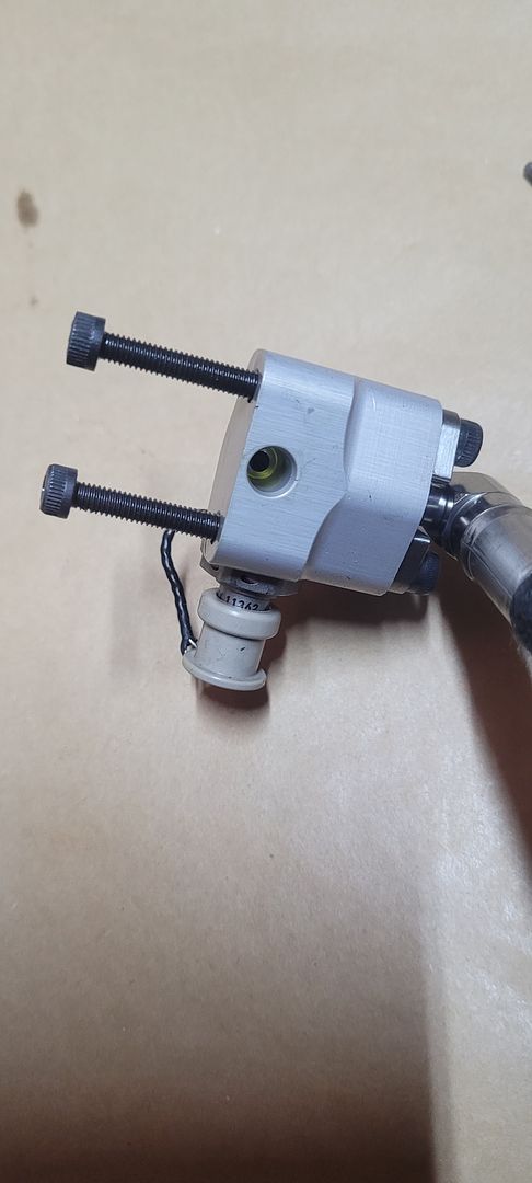
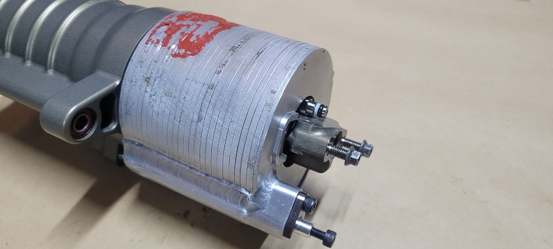
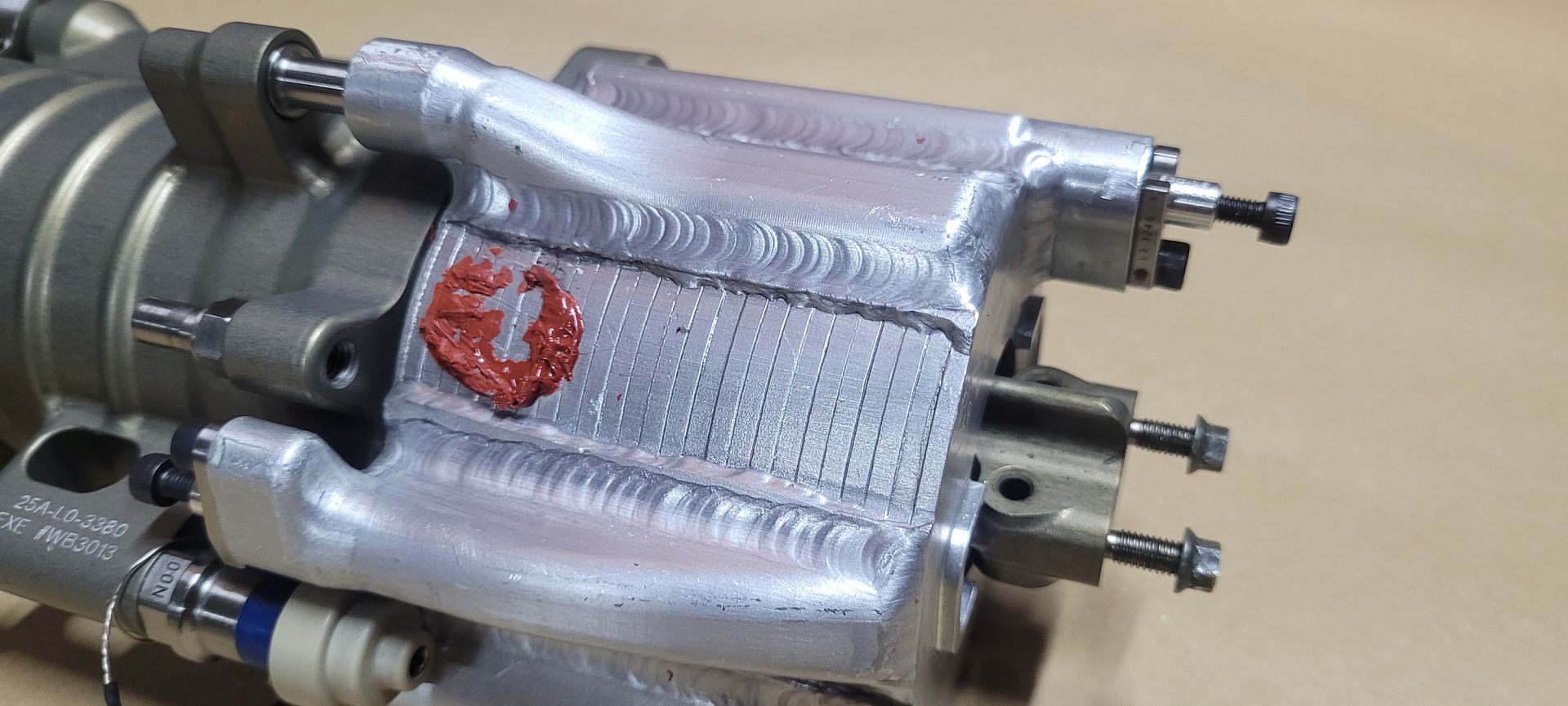
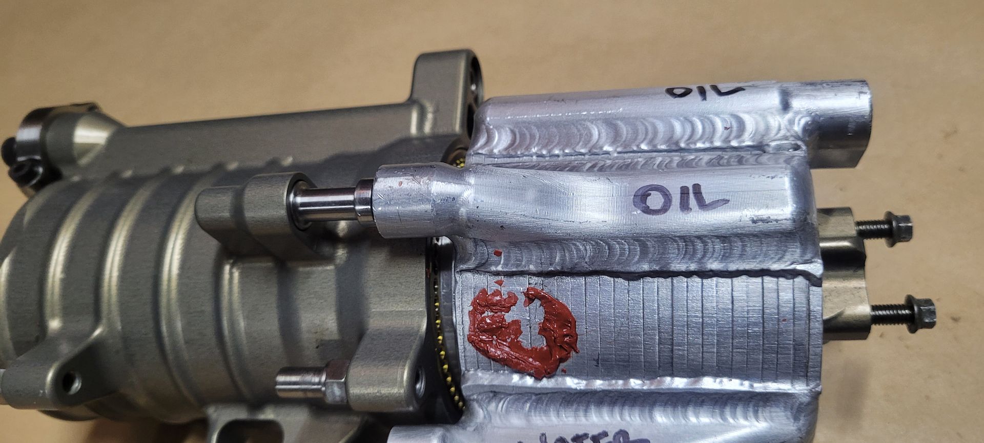
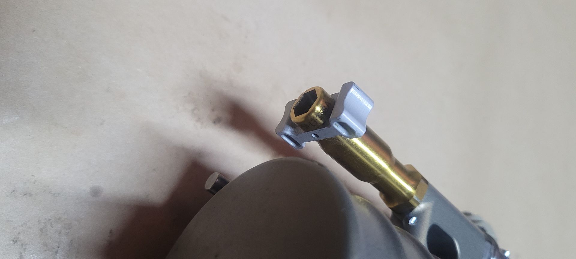
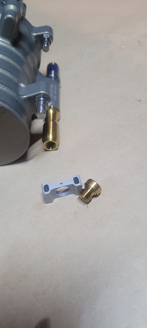
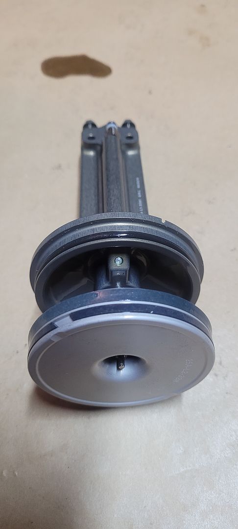
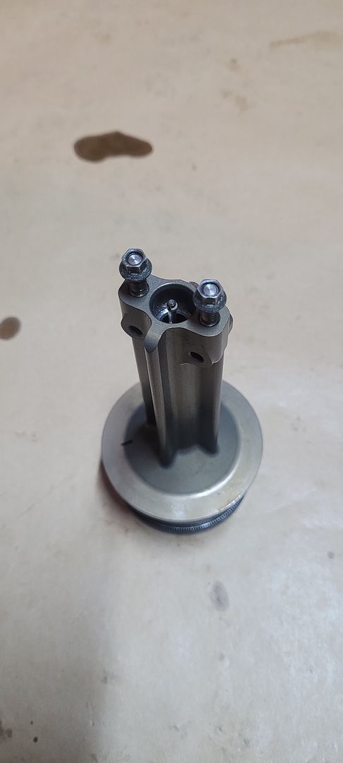
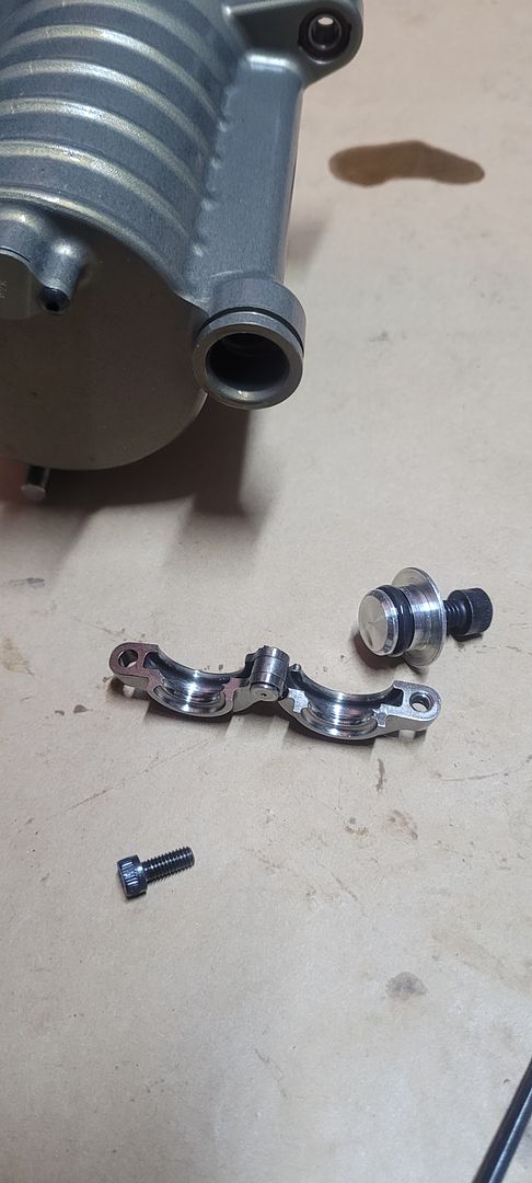
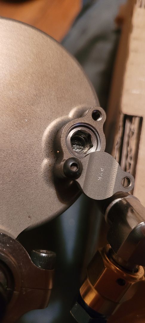
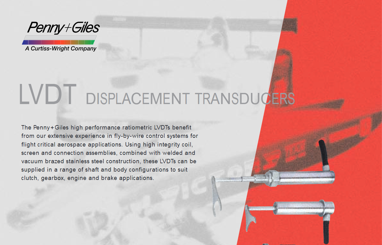
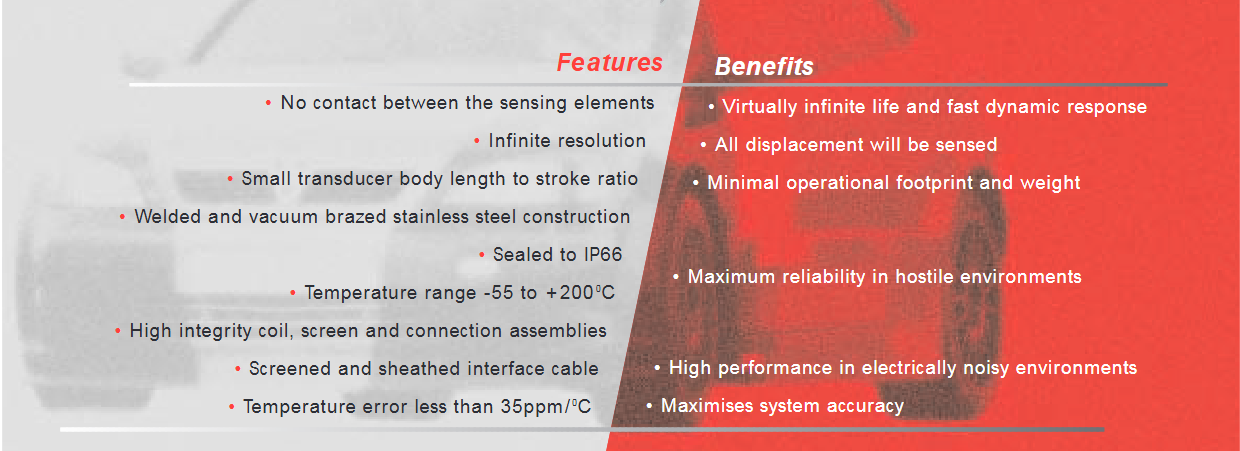
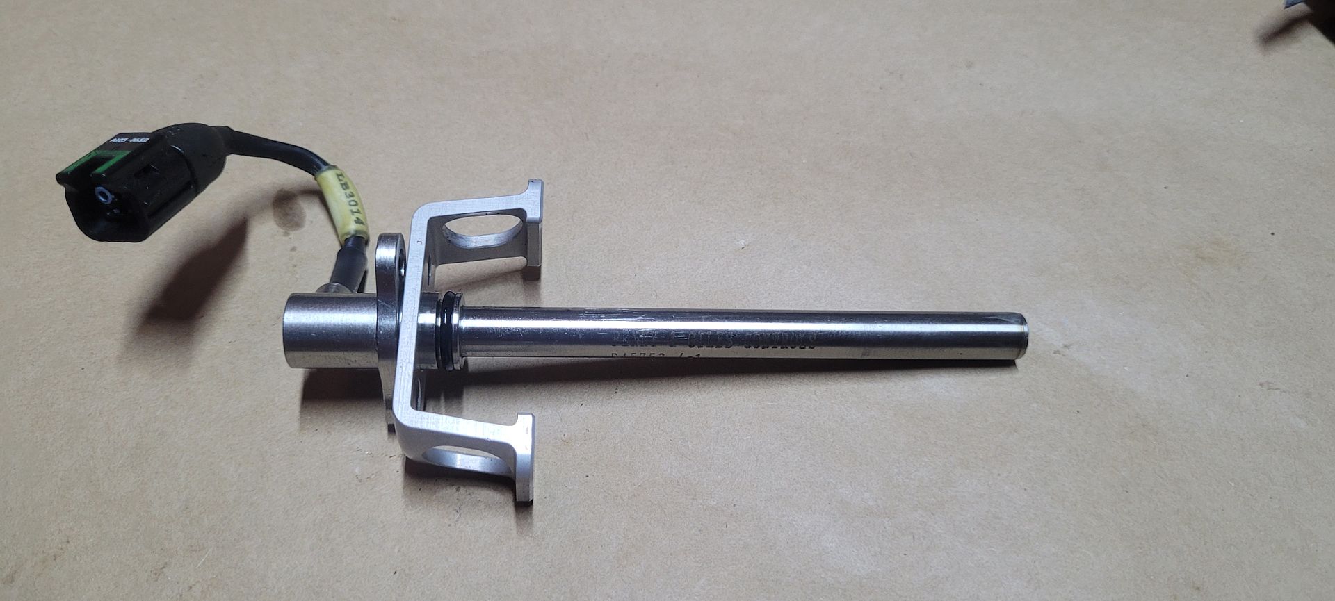
The bridge carrying the linear displacement transducer was then removed, this sensor accurately measures the position of the piston within the accumulator body. The sensor is from Penny and Giles,

Image

Image

Image

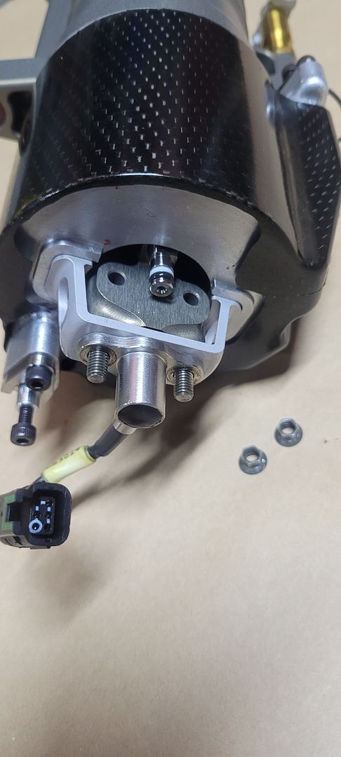
Take note of the two small shims that were under the sensor bridge - these are required to accurately calibrate sensor end position vs piston max travel position. This deviation is caused by tolerance stack up due to it being mounted onto the oil to water heat exchanger which is a weldment/diffusion bonded item,

Image

Image

Image

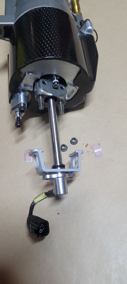
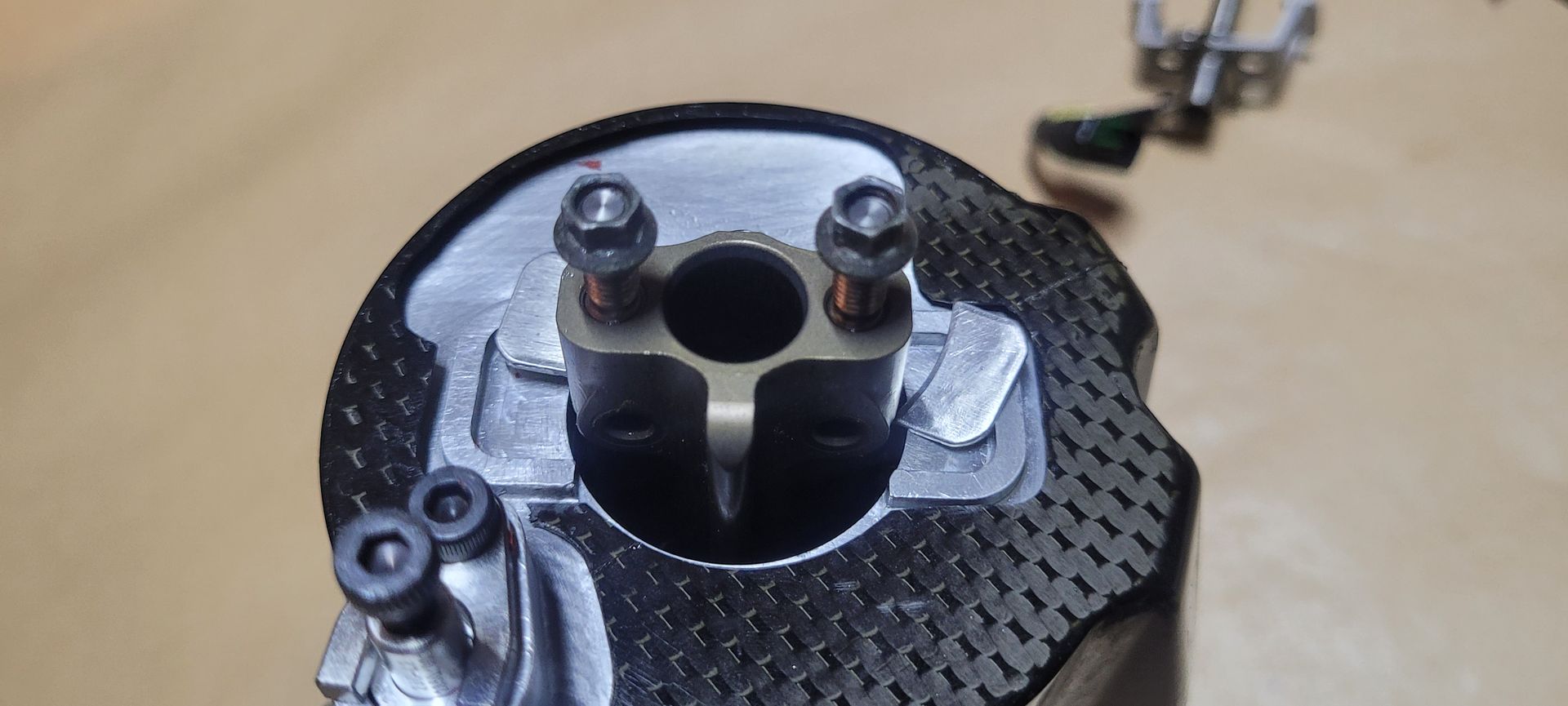
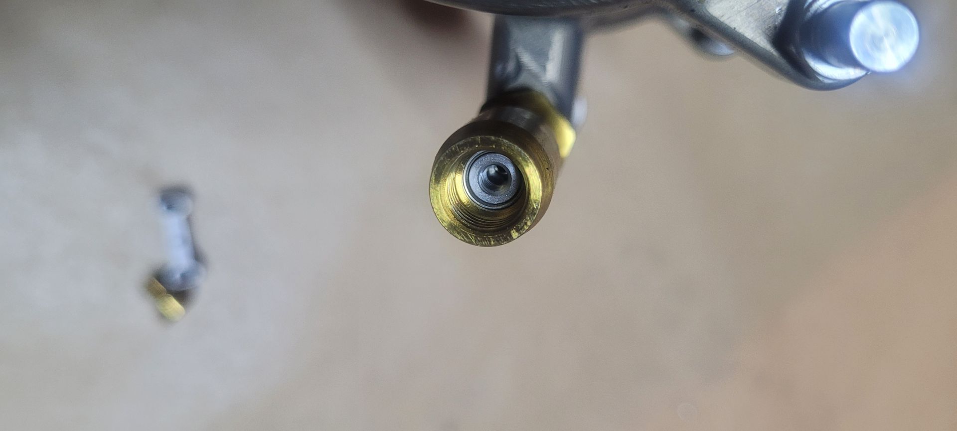
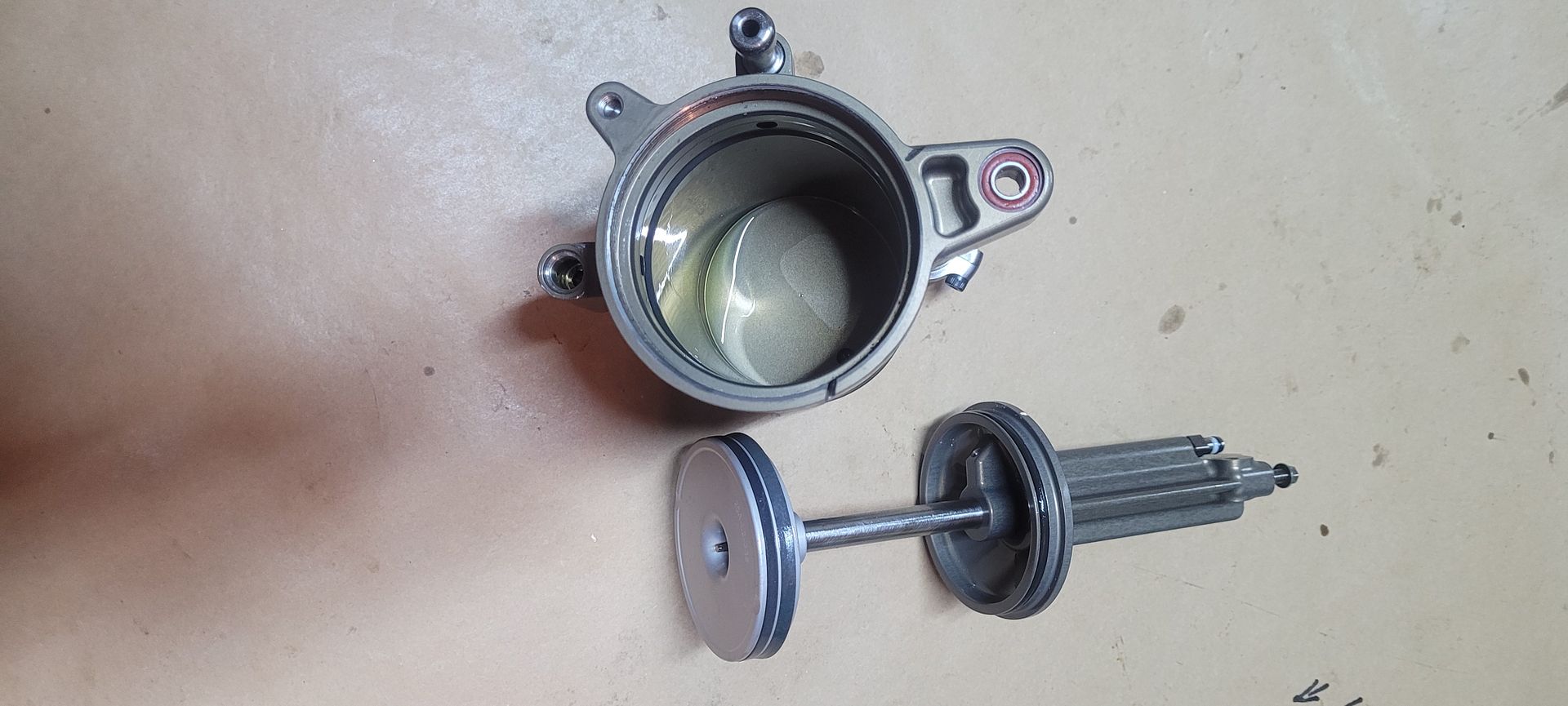
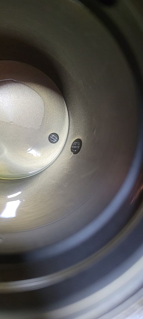
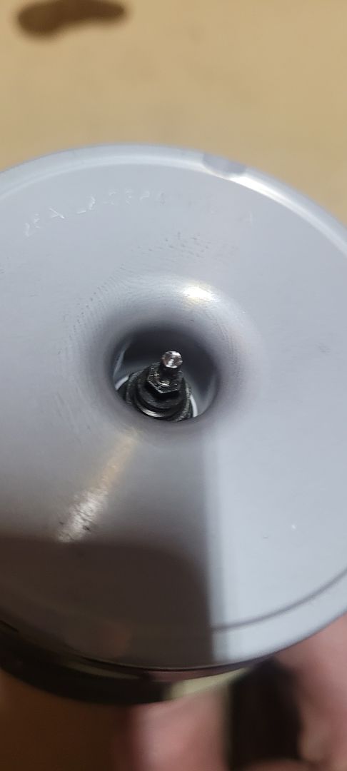
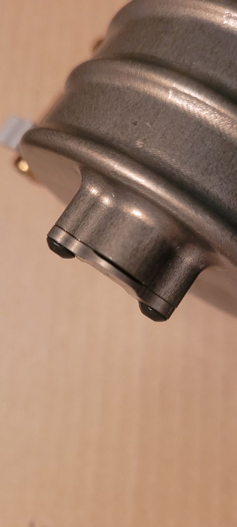
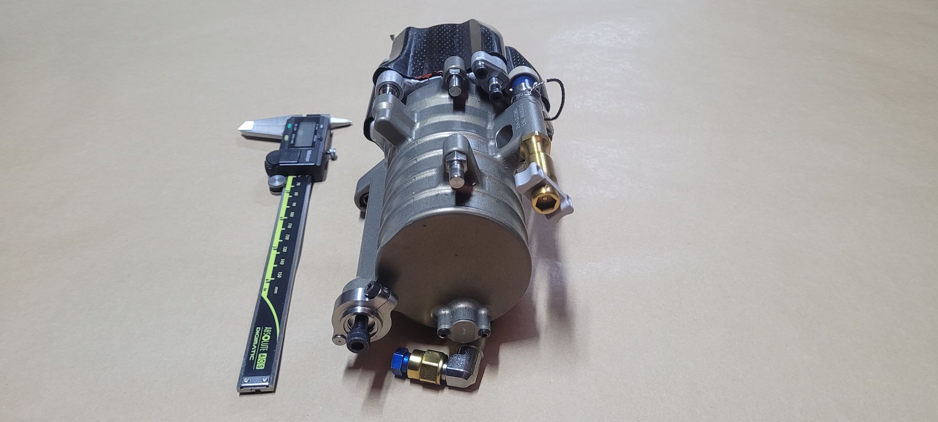
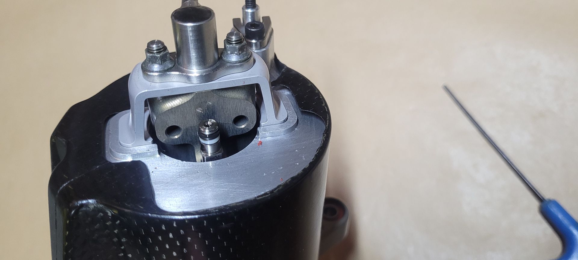
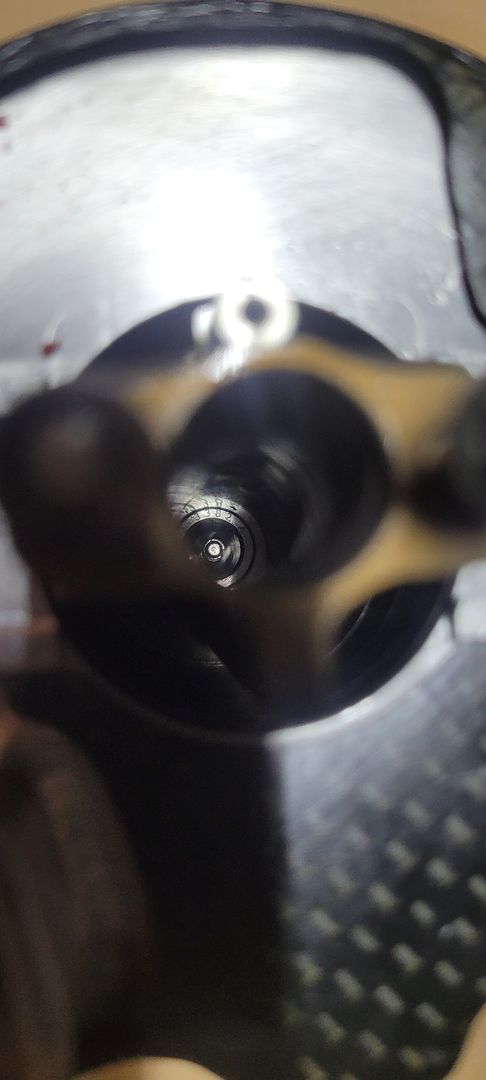
The internal traveling part of the transducer can now be seen deep down in the accumulators piston rod,

Image

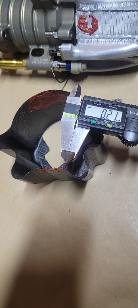
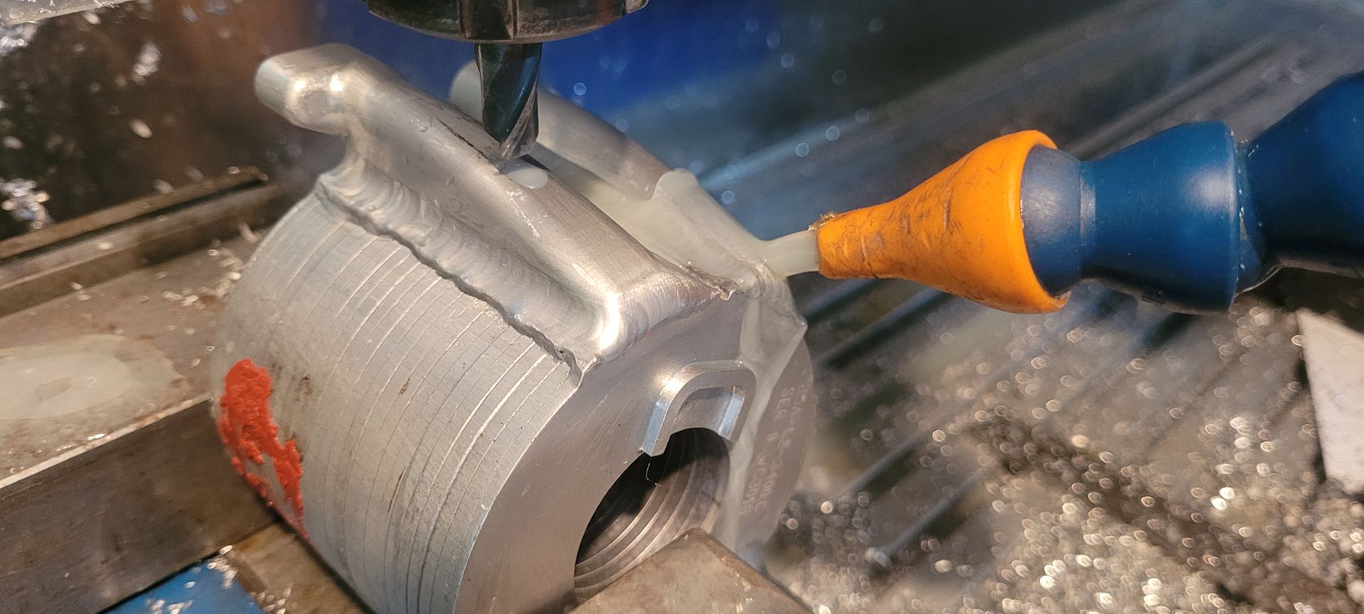
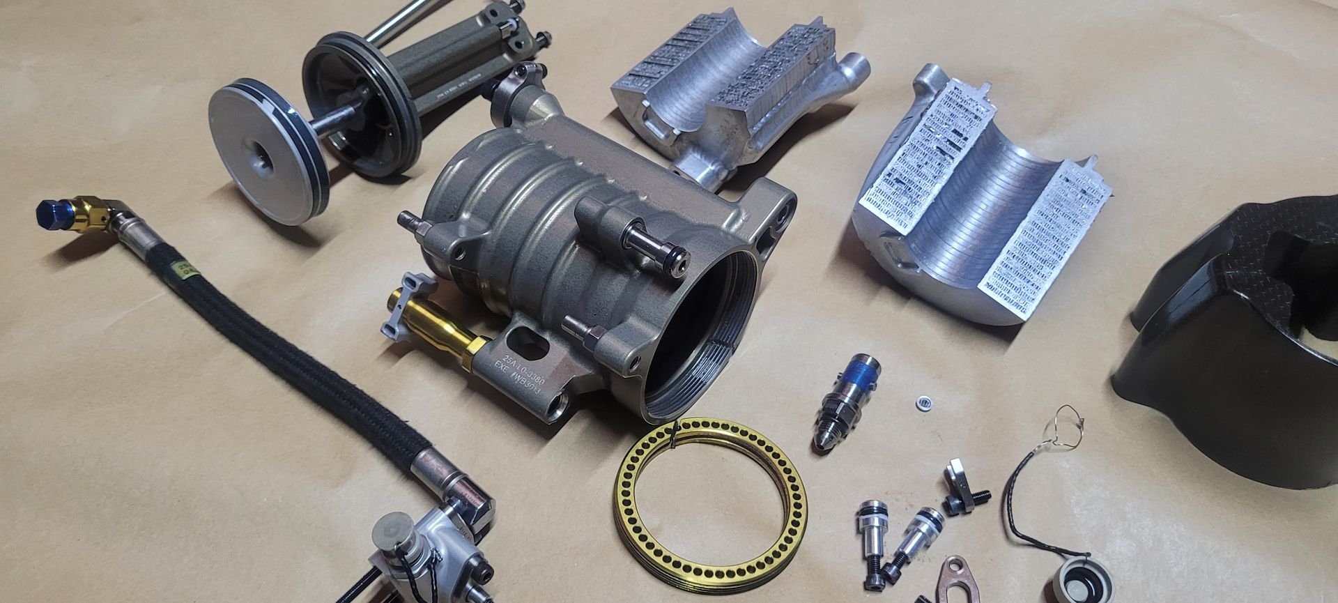
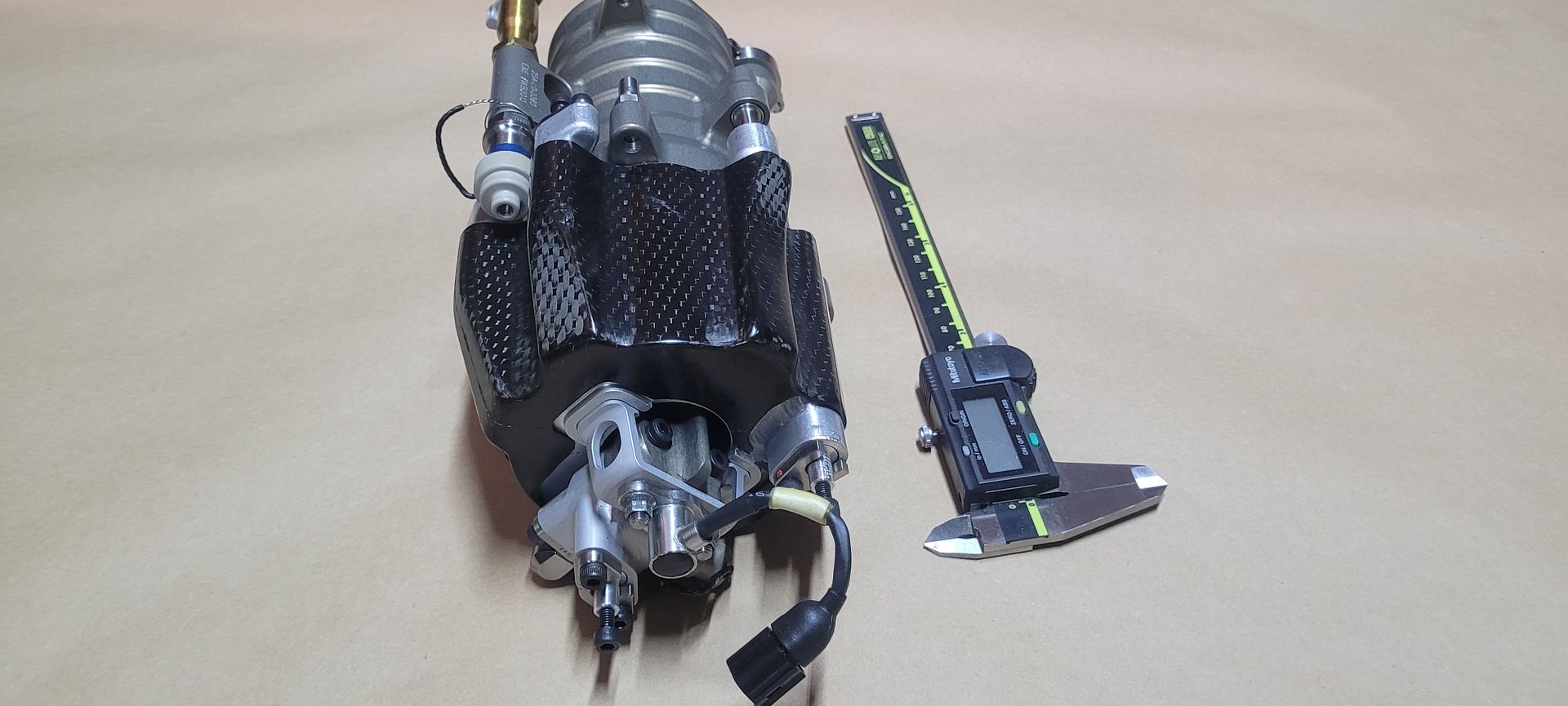
With those parts out of the way the carbon cover could now be removed, it is held on with RTV Silicone in a few areas,

Image

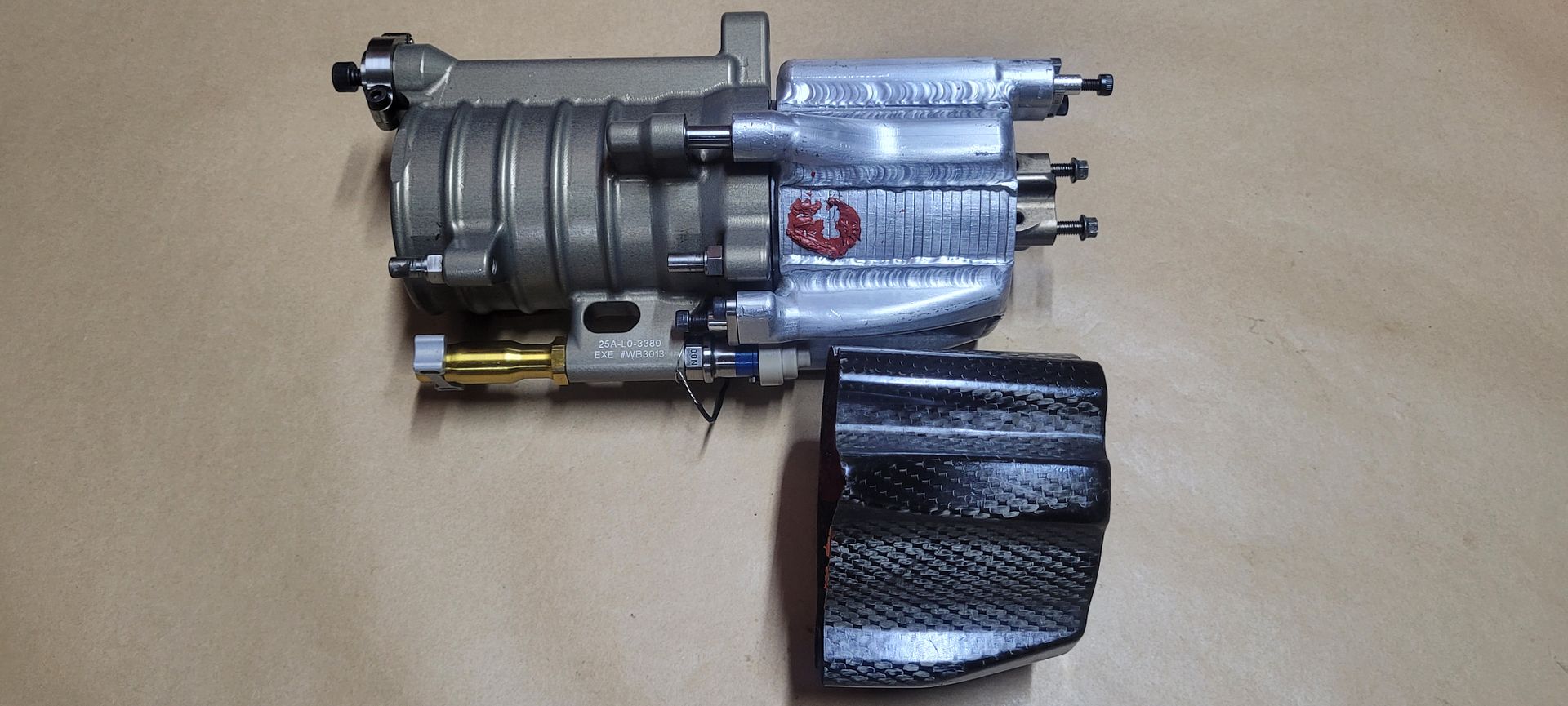
Worth noting this is the thinnest carbon part I've ever come across, as light and as fragile as a paper cup,

Image
Last edited by Brian.G on 31 Jan 2023, 15:00, edited 1 time in total.
If you think you cant, you wont, If you think you can, you will

Brian.G
Brian.G
334
Joined: 10 Dec 2010, 23:52
Location: Ireland

Re: F1 Hydraulic Oil Heat Exchanger, a closer look

Post

The heat exchanger is now totally visible,

Image

Image

Image

The stackup of the lamination passageways,

Image

Both units now separated,

Image

Image

Image

The coolant bungs removed,

Image

A quick test with brown paper was done just to fully verify what ports were what - both coolant and oil will 'wet' brown paper and turn the paper a much darker colour, however, when both samples are then heated with hot air, the oil soaked sample will not resort back to the original colour whereas the coolant/water soaked sample will. Its an easy test that can be done quickly,

Image

A quick fitup again showing what goes where,

Image
Last edited by Brian.G on 31 Jan 2023, 06:16, edited 1 time in total.
If you think you cant, you wont, If you think you can, you will

Brian.G
Brian.G
334
Joined: 10 Dec 2010, 23:52
Location: Ireland

Re: F1 Hydraulic Oil Heat Exchanger, a closer look

Post

Mounted on the CNC both a coolant manifold, and an oil manifold were machined away to get a look at the exchanger internals.

Left hand coolant manifold first,

Image

Image

Image

And then an oil manifold, apparent now, and not anything too unusual, both fluids take different paths, separated by partitions,

Image

Image

The exchanger halved with a slitting saw now shows the pathways clearly - every second section being the same fluid path,

Image

Image

Onto the accumulator itself, and a quick note on why accumulators are required...

An accumulator is nothing more than a tank, separated into two sections - the separator can be a moving piston, or a diaphragm membrane. On one side there is oil, the other side pressurized gas - usually nitrogen. Since the hydraulic system on an F1 car is closed - once the oil heats up it gets larger and therefore needs room to expand. The same issue occurs when a small actuator is being moved within the system. Often times if these actuators are double acting miniature hydraulic rams, the volume of oil below the piston will be greater than the volume above the piston due to the piston rod occupying space, and that space or volume varying at a different rate as the piston rod extends or retracts in and out of the cylinder. This is also the reason why a digger can lift more than it can pull down, as the oil force area is greater below the piston vs on top of the piston due to the piston rod taking up available oil force area.
The accumulator also acts as a dampener from hydraulic pump pulsations which may otherwise be translated to actuators and piping causing damage. Similar in fact to how flexible artery walls smooth heart pulsations before the blood reaches thinner walled more fragile arteries in your brain and elsewhere. Harding of the arteries with age causes these pulsations to be transmitted further along, and into the finer arteries, thus causing rupture in time, and possible strokes.

So with all that in mind they are relatively simple items,

Image

Some of the fittings were removed first,

Image

Image

A one way valve inside supplied by LEE COMPANY - micro hydraulics specialists,

Image

Image

A dry break the other end,

Image

The layout,

Image

Onto removing the titanium retainer ring, had no pin spanner the correct size so just zipped it in one place with a 1mm disc,

Image

Piston assembly removed - all oil ways enter/exit above the piston as to be expected,

Image

Super finished honed bore as mention earlier,

Image

The inside of the gas filling port - a tiny 5mm diameter filter can be seen on the inlet, also from LEE COMPANY,
(its reflection on bore wall to the right)

Image

The filling port bung on the outside,

Image

The filter details,

Image

A look at the piston and shaft,

Image

Image

The dual nut setup - small nut holds transducer sensor stem rod, the larger nut holds piston to rod,

Image

The top of sensor stem rod,

Image

One very expensive titanium coupling retainer,

Image

Image

An overview of the many parts,

Image

Image

Image


While I would like to cad up the passage ways and show you the routes and drillings in detail - there is simply no point as I have no idea where they go to in terms of routing on the actual car so it would be too much of a risk to go guessing.
As it is, I'm not overly happy with the LEE COMPANY one way valve function situated in the gold fitting, as it would appear it would blow off oil to atmosphere. (Perhaps that is intended and used when filling the system)
Also not content with the Nitrogen fill port in the base with the tiny LEE COMPANY filter - externally it has a flat bung plate as shown below, with reliefs - not airtight, with just a retainer hollow grub holding in the filter. Perhaps this was removed and a nitrogen fill fitting installed.

Image

Image

Both of this anomalies could be however transit fittings - which are common, whereby the part is taken out of service and sealed but allowed breath, should it need to be returned to service.

Happy reading, and all the best for 2023,

Brian,

Ps - Not affiliated in any way with Penny and Giles, or LEE COMPANY.
If you think you cant, you wont, If you think you can, you will

User avatar
_cerber1
239
Joined: 18 Jan 2019, 21:50
Location: From Russia with love

Re: F1 Hydraulic Oil Heat Exchanger, a closer look

Post

Thank you very much for this engineering art. =D> =D> =D>

johnny comelately
johnny comelately
110
Joined: 10 Apr 2015, 00:55
Location: Australia

Re: F1 Hydraulic Oil Heat Exchanger, a closer look

Post

Have to ask the dumbest question, but is that cooler design something akin to the reaction engine intercooler design?
Probably not as fluid to fluid but any explanations re the would be appreciated by cooling experts

Brian.G
Brian.G
334
Joined: 10 Dec 2010, 23:52
Location: Ireland

Re: F1 Hydraulic Oil Heat Exchanger, a closer look

Post

Johnny, its just a basic plate heat exchanger design? In the first image where its milled open - where there are fins, that's a common area for fluid - every second ''band'', where theres solid metal between the fins, are actually just more fins, but incased in partitions...and where the other fluid circulates...

https://www.kobelco.co.jp/english/ktr/p ... 51-056.pdf - Should link stop working, searching ''diffusion bonded heat exchanger'' will bring back plenty of details.

Image

Brian,
If you think you cant, you wont, If you think you can, you will

User avatar
henry
324
Joined: 23 Feb 2004, 20:49
Location: England

Re: F1 Hydraulic Oil Heat Exchanger, a closer look

Post

Thanks for a fascinating insight @Brian.G.

The process to diffusion bond metals has been in use in Japan for 300 years. I don’t know how much this knowledge base has contributed to the ability to make these heat exchangers but I’m guessing it doesn’t hurt.

I would think that a component like this might well nowadays be a candidate for 3D printing, assuming a suitable material is available. I know that injection moulding dies are printed with intricate cooling channels albeit in managing steel.
Fortune favours the prepared; she has no favourites and takes no sides.
Truth is confirmed by inspection and delay; falsehood by haste and uncertainty : Tacitus

Brian.G
Brian.G
334
Joined: 10 Dec 2010, 23:52
Location: Ireland

Re: F1 Hydraulic Oil Heat Exchanger, a closer look

Post

TWI UK seems to be the go to place for these kind of high end/aero parts.

Brian,
If you think you cant, you wont, If you think you can, you will

johnny comelately
johnny comelately
110
Joined: 10 Apr 2015, 00:55
Location: Australia

Re: F1 Hydraulic Oil Heat Exchanger, a closer look

Post

henry wrote:
31 Jan 2023, 18:48
Thanks for a fascinating insight @Brian.G.

The process to diffusion bond metals has been in use in Japan for 300 years. I don’t know how much this knowledge base has contributed to the ability to make these heat exchangers but I’m guessing it doesn’t hurt.

I would think that a component like this might well nowadays be a candidate for 3D printing, assuming a suitable material is available. I know that injection moulding dies are printed with intricate cooling channels albeit in managing steel.
Honda used it in their F1 last era for titanium conrods which were two piece and hollow and uses pressure and temperature until there is molecular bonding

saviour stivala
saviour stivala
48
Joined: 25 Apr 2018, 12:54

Re: F1 Hydraulic Oil Heat Exchanger, a closer look

Post

Although a different process, Honda also fused together machined pieces of a hollow build-up crankshaft at the time mentioned. Years later a Cosworth top engine man was talking to RET about hollow-out crankshafts and he said that it is not possible to drill a bend hole to hollow-out a crankshaft.
Last edited by saviour stivala on 01 Feb 2023, 00:15, edited 1 time in total.

User avatar
PlatinumZealot
550
Joined: 12 Jun 2008, 03:45

Re: F1 Hydraulic Oil Heat Exchanger, a closer look

Post

Awesom post as always. Well narated. =D>

It does seem overly complicated all in the name of measuring the exapnsion of the fluid!
🖐️✌️☝️👀👌✍️🐎🏆🙏