Caito's Dune buggy

Post here information about your own engineering projects, including but not limited to building your own car or designing a virtual car through CAD.
Caito
13
Joined: 16 Jun 2009, 05:30
Location: Switzerland

Caito's Dune buggy

Post

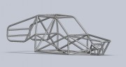
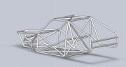
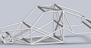
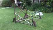
Hello guys, a couple of friend and I decided to build a dune buggy. We are going to design the front and rear suspension. Front is double A-arm, with a fiat 600 upright. Rears is mc-pherson with fiat 128 upright.

It will have a 1.3 liter engine from a fiat 128. The project is quite cheap, a first project. Nothing really extravagant, nor to jump 100m. A tough dune buggy that will climb and tolerate some small jumps.

I would like to know which should be our goals in term of suspension movement.
For the moment I'll focus on the front of the car.
For example wheel travel. 40cm is enough? Of that 40cm, I guess we would need 25cm for bump, and 25cm for droop, is that logical?

Should we minimize camber variations(i.e. long a-arms), bump stter(short steering rack)?

What's a logical wheel steering angle?


I have some basic idea, but I've never worked with dune buggy's so I don't know where to aim, yet. Anything you have to add, advice or whatever is more than welcomed.


Thank you very much!

Caito.


PS As soon as I finish suspension design I'll start buggin' with chassis :p
Come back 747, we miss you!!

User avatar
747heavy
24
Joined: 06 Jul 2010, 21:45

Re: Dune buggy

Post

You could consider a trailing arm front suspension instead - IMHO
It´s quite popular with off road buggies, as the wheel will move
backwards on inpact with an obstacle, and you don´t have to worry about
camber change over wheel travel.

Semi trailing arms at the rear perhaps.

Just a thought

good luck:

Image
Image
Image
"Make the suspension adjustable and they will adjust it wrong ......
look what they can do to a carburetor in just a few moments of stupidity with a screwdriver."
- Colin Chapman

“Simplicity is the ultimate sophistication.” - Leonardo da Vinci

Caito
13
Joined: 16 Jun 2009, 05:30
Location: Switzerland

Re: Dune buggy

Post

Thanks for the reply 747. We're attached to the mchpherson rear cause we'are using the front of the fiat128, put in the rear. Getting hubs and everything, correct splines, etc for a semitrailing arm would be more difficult. For the rear we just need to make one wishbone(the same as a semitrailing) and decide where to put the strut.


As for the front, with the current upright it would be impossible(not impossible but strictly nonsense) to have trailing arms at the front. We'd also like to learn about double A-arms for the future(for future, racing projects. but first we need to start with simpler things, a buggy). It'll look killer too.

For the moment we have 25cm bump, 15cm droop. In bump there's 0.5°change in camber in the whole 25cm, with a little over than 1° in droop. camber change vs roll is 1:1. 4 degrees of camber with 4 degrees of roll.(due to almost equal and parallel arms).

Half-track change is quite a lot, but there's not much to do in that respect, with the big wheel travel we're working. We're limited to 1.30m of track in the rear so we're going with 1.30 in the front. Would you suggest going with more, 1.4 lets say? That would give larger wishbones and probably larger control.

Haven't analyzed roll center yet, but will soon.

I'll keep you updated. Are we aiming correctly in terms of suspension design?

Bye bye

Caito!
Come back 747, we miss you!!

countersteer
9
Joined: 28 Apr 2007, 14:37
Location: Spring Hill, TN

Re: Dune buggy

Post

I'm not a big fan of off road racing but have always marveled at the extremely long control arms on the front of the top notch buggies and trophy trucks used in the SCORE racing series. I'd google up images from the Baja 1000 and possibly some technical articles. I recently read an article on the inner workings of a Trophy Truck that was very informative.

Keep in mind that some of the lesser more restricted classes may use a particular design (the trailing arm beam front suspension from a VW beetle for example) as it is required by the rules and may not be the best solution. It doesn't sound like you are restricted by such.

Sounds like a really fun project.

Caito
13
Joined: 16 Jun 2009, 05:30
Location: Switzerland

Re: Dune buggy

Post

Hi! Here are some pics of the chassis we're planning to build. It's not 100% finished but that's the general idea. Some tubes are purely for aesthethical reasons, most are not. I leave a solidworks file for public scrutineering. Any input is more than welcomed. If there's anything you would add/remove just let me know. In the sketch there's a general layout for the suspension. Double a arms front, trailing arm rear.

Image Image Image Image Image Image


Solidworks file: http://www.4shared.com/file/XELsFM1G/Chassis3.html


My real doubt is I don't know which tube to use. I'm actually planning 44.45mm(1.75inch) x 2mm. Is it too much, too little? Would you change diameter, thickness, both?

Thank you very much!

bye bye.-
Come back 747, we miss you!!

mx_tifoso
0
Joined: 30 Nov 2006, 05:01
Location: North America
Contact:

Re: Dune buggy

Post

You have made two threads for the same project and left us "hanging" in both! :)

Any updates?
Forum guide: read before posting

"You do it, then it's done." - Kimi Räikkönen

Por las buenas soy amigo, por las malas soy campeón.

Caito
13
Joined: 16 Jun 2009, 05:30
Location: Switzerland

Re: Dune buggy

Post

Ohh... oops. So it wasn't a DejaVu, it was real that I made another post :p, sorry.


We're a group of 3. The other 2 owed a couple of final exams, and now one of them got really sick.

Today(or tomorrow) some more tubes are arriving. 1,75inch x 2mm, cold rolled. We already made templates for tube cutting. You convert them to sheet metal, make a drawing, print it and stick it to the tube. As it's too complicated we're going to buy a cheap-chinese plasma cutter for the job.


So hopefully we will start during the weekend building the chassis.


Bye!

Caito.-
Come back 747, we miss you!!

Caito
13
Joined: 16 Jun 2009, 05:30
Location: Switzerland

Re: Dune buggy

Post

Hey guys, we got the plasma cutter and did some tests. The cutter works awesome but we have a design problem.

Lets say we want to join a tube to another at 90 degrees. Solidworks does the fishmouth and we get the template to cut it. We print it, mark the tube, cut. And voila.. it doesn't fit.

It doesn't fit because the inner part of the tube should(theoretically) be cut differently than the inner part. So we said, instead of printing the outer cut, lets print the inner cut. The thing is the inner cut is smaller(smaller radius, hence, smaller perimeter) and should be sized so it can be put in the outside of the tube so we can mark it and cut it.

We will try tomorrow if this works. For the moment, is there any better solution?

Here you can see the problem:
Image
Come back 747, we miss you!!

Caito
13
Joined: 16 Jun 2009, 05:30
Location: Switzerland

Re: Dune buggy

Post

Didn't work. It just needs grinding anyway.
Come back 747, we miss you!!

Caito
13
Joined: 16 Jun 2009, 05:30
Location: Switzerland

Re: Dune buggy

Post

The think starts to get a shape:

Image


It already has a waiting engine+gearbox:
[youtube]http://www.youtube.com/watch?v=VxmwNhbHA6M[/youtube]
Come back 747, we miss you!!

Caito
13
Joined: 16 Jun 2009, 05:30
Location: Switzerland

Re: Dune buggy

Post

http://www.facebook.com/photo.php?pid=3 ... 1282581128


That's how it looks at the moment.


PS: Cant his thread be moved to the Automotive section?
Come back 747, we miss you!!

User avatar
mep
29
Joined: 11 Oct 2003, 15:48
Location: Germany

Re: Dune buggy

Post

Nice progress, sad you get so little comments.
Keep us up to date.

Caito
13
Joined: 16 Jun 2009, 05:30
Location: Switzerland

Re: Dune buggy

Post

Work is going slow (hard university, you know..) but it still runs.


I have a question, we have to join two round tubes to make, lets say, a longer one.

Should we just weld them, or do something better to reinforce them?

PS: Just in case, we have to join then because there is some complex bending and it's much much easier to do two bend separately and then join the tubes.
Come back 747, we miss you!!

spacer
9
Joined: 01 Nov 2009, 20:51

Re: Dune buggy

Post

I'd insert a inner tube that tightly slides into both tubes. Perforate the two tubes so you can weld the tubes together over a wider area.

This will also help you keeping the two tubes colinear.

Caito
13
Joined: 16 Jun 2009, 05:30
Location: Switzerland

Re: Dune buggy

Post

I agree with you spacer, that would be ideal but it's out of our league. We are working at home in a small shop with just the minimal stuff.

What I actually though was putting some strips and do the holes and weld them. That would work out cool for tension but not for bending. Those tubes shouldn't receive any bending force anyways.

In the worst case we would put some some other ugly reinforcements.


Let me come up with another question. The suspension is going to have silent blocks in the pickup points. We found some silent block that tightly fit in the tube we chose for the suspension arms. The thing is that the tube where the silent block is inserted must be welded. Given that we don't have access to a lathe or similar machinery it would be preferable to insert the silent block before welding. The problem is that I don't know if the rubber would hold up the heat.


If we weld before and insert the silent block later we risk that the tube deforms and the silent block won't fit.

Any suggestions?


bye bye!

PS Just in case, here's a pic of a silent block similar to the one we are going to use.
Image
Come back 747, we miss you!!