Variations of vortices: vicious or virtuous?

Smoke visualizing rear wing tip vortex in wind tunnel, source: http://techf1les.files.wordpress.com/20 ... d-drag.gif
Before continuing (or even after) it may be beneficial to read some of the previous articles in this series on aerodynamics applied to F1:
What is a vortex?
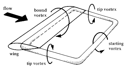
Very simply, a vortex is defined as a region of fluid which is rotating around a core of low pressure. Vortices are a side effect of producing aerodynamic lift (or downforce) with wings, starting from the circulation of the bound vortex , where the circulation is proportional to the lifting force:
,
where is the lift force in newtons,
is the density of the fluid,
is the freestream velocity, and
is the span of the wing.
Author’s note: It may be helpful to think of circulation in terms of the Magnus effect. If a circular cylinder, spinning about the centre of the circular base, is set perpendicular to the direction of travel, it will generate a lift/downforce; as the air attached to the spinning cylinder is pushing against the air trying to flow over it on one side, slowing it down = high pressure, and works with the direction of flow on the other, speeding it up = low pressure. A rotating cylinder has the same behaviour as a forced vortex, where the angular velocity is linearly proportional to the radius of the rotating body. This doesn’t even require a physical body to work, so if a region of fluid in CFD was defined as a forced vortex, the streamlines through the rotating fluid would bend and a force would be produced in the fluid.
To balance the system the bound vortex has a counter-rotating counterpart - the starting/shed vortex - which along with the trailing vortices, as the air from the high pressure side spills over to the low pressure side, which then forms a vortex ring. A downforce generating wing has the opposite circulation (negative lift) to lifting wings, so the vortices rotate in the opposite direction, i.e. the tip vortices rotate with centreline up-wash.
Source: https://www.princeton.edu/~maelabs/hpt/ ... /y45-0.gif
Tip vorticity is a major source of drag for high lift wings - known as induced drag . Induced drag is inversely proportional to the aspect ratio of the wing,
,
where is the drag coefficient,
is the lift coefficient, and
is the aspect ratio -or the ratio between wing span
and chord
,
,
assuming that the wing is rectangular, i.e. the chord is a constant length. Conversely aspect ratio can be defined by,
is the planform area of the wing.
Formula 1 rear wings are low aspect ratio, AR = 2.7 (rising to 3.0 with the span increase in 2019), even when compared to other race series - for example, Le Mans Prototypes (AR = 7.2) or GT racers (AR = 6.0) - let alone compared to aviation. In general, the higher a wings aspect ratio, the more “efficient” the lift or downforce; which is partially why the T-wing was adopted by many teams last year. Because of the high number of low aspect ratio wings, induced drag is one of the biggest sources of aerodynamic drag on a Formula 1 car, with the rear wing tip vortices in particular being a significant constituent of the aerodynamic wake behind it.
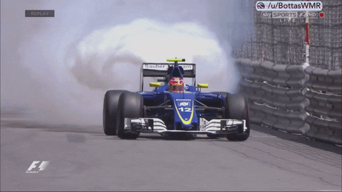
Rear wing vortex pair in wake highlighted by blown Ferrari engine in Felipe Nasr’s Sauber C35, source: https://media.giphy.com/media/3o6EhRHS3 ... /giphy.gif
The strength of the tip vortex can be reduced by decreasing the circulation towards the tip, for example an elliptical wing, such as on a Spitfire or the front wing on the 1971-72 March 711, will also have an elliptical spanwise lift distribution - with peak circulation on the centreline dropping in a gradual curve to zero circulation at the wing tips- so will have weaker tip vortices than a wing with a rectangular lift distribution - the same circulation at every spanwise point. However, this also reduces the absolute lift available from a wing of equal span, chord, and camber, so the wing size or camber have to be increased to produce the same lift, which in Formula 1, where the position and size of wings are heavily restricted is not ideal.
Another way to reduce the tip vortex is by using an endplate. An endplate increases the effective span of a wing, reducing induced drag without actually increasing the span. The endplate prevents flow from leaking from the high pressure side to the low, as the pressure on the outside of the endplate is closer to atmospheric. Instead of forming around the tip of the wing the vortex instead forms on the outer surface of the endplate, however, a secondary vortex is formed on the lowest extreme of the endplate which curls in towards the centreline of the wing assembly due to the pressure outside the endplate being higher than the suction on the low pressure side of the wing elements.
Formula 1 cars generally have the power to overcome the drag penalty from the rear wing tip vortices, as the increased downforce is typically more beneficial to overall lap time. However, at circuits where high downforce along with higher lift-to-drag ratios are required, such as Spa, Azerbaijan, or Canada, teams will often run a spoon/bucket shaped wing, with less camber, incidence, or both at the outer extremes of the wing than at the centreline. This works along the same principle as an elliptical wing, where the reduced circulation towards the tips helps reduce the induced drag, albeit at the expense of peak downforce across the fixed span.
Vortices themselves have circulation, so can be used to produce lift. An example of this is the delta wing - which despite the name does not have an aerofoil profile like a traditional wing section. Delta wings create lift at high incidences using the low pressure cores of vortices. There are a number of examples of delta wings and use of vortices to produce a force on a Formula 1 car, which will be summarized later.
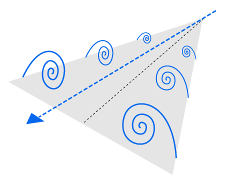
Delta wing vortices, source: https://upload.wikimedia.org/wikipedia/ ... vortex.png
Visions of Vortices
The weather can sometimes make the low pressure core of vortices visible to the naked eye, when the air pressure is low enough (high altitude, low air temperature, and inclement weather systems all reduce air pressure) to condense the water vapour in the vortex core, revealing the normally invisible science of aerodynamics. Aircraft contrails are a familiar sight to anyone who has so much as glanced at the sky, while in Formula 1 the most familiar example is the rear wing trailing vortex pair, and since 2009 the front wing y250 vortex system.
Contrail of y250 vortex core from front wing of 2012 Red Bull Racing RB8, source: https://media.giphy.com/media/hBf0C62t5kPHW/source.gif.
There are a number of ways of visualizing a vortex in CFD, one is to look for the low static pressure of the core. This approach is normally used with 2D contour plots of total pressure in the flow field, where the low static pressure will have a negative value, but this method is not particularly satisfactory in 3D. Another method is simply to visualize the vorticity quantity, this can be problematic as vortices have sign, i.e. they rotate in both clockwise and anti-clockwise directions. They are also not only present in one direction, some vortices have their cores stretching in the streamwise (along the length of the car, or x-direction in the standard coordinate convention), while some sit transverse to the flow (a rolling vortex). It is possible to only visualize the vorticity around a single axis, but again this is not entirely satisfactory, for example the y250 vortex is deliberately shaped to move outboard between the front tyre and the front of the sidepods, so does not purely rotate about the x-axis. Setting streamlines can show where the flow is rotating, assuming the streamlines are seeded in the right position and with sufficient density, but does not give any particular value which quantifies the vortex. The normal method for 3D visualization of vorticity is to set isosurfaces of lambda2 or Qcriterion (below), setting the value of the isosurface sufficiently high to only show the strongest regions of vorticity - regardless of the direction of rotation.
[em]Author’s note: these two variables are just different definitions of defining “what” a vortex is: lambda2 methods separate out the velocity gradients in a flow into components and then only look at the amount of “spin” and the strain-rate in the flow, whereas Qcriterion defines a vortex as being anywhere with vorticity magnitude larger than strain-rates in the flow with a lower than freestream pressure. There exist many other methods as well, such as helicity, swirl parameter, eigenvector methods, among others, but the only difference between each method is how it defines what to show you in your post-processor as being classified as a “vortex”.[/em]

Isosurfaces of vortices (either Qcrtierion or lambda2) around a 2013 Sauber C32 F1 car, source: https://www.youtube.com/watch?v=pREgFVRXeDI
How teams use vortices for benefit
Despite the negative side effect of induced drag, vortices have been shown to be extremely beneficial to a Formula 1 car’s aerodynamic package, when used correctly. A well known vortex in F1 is the Y250, named after the width of the FIA front wing section as defined in the regulations. The Y250 is developed along the length of the monocoque using turning vanes and the bargeboards, and helps to push the wake of the front tyre away from the floor, improving the capacity of the floor to produce downforce. Below is a comparison of the Y250 shape when removing the front suspension arms, a small change to the shape of the Y250 has resulted in a significant change of the tyre wake, affecting the cooling intakes and even to the rear coke and diffuser.
 Comparison of Y250 vortex shape and effect on tyre wake from removing suspension arms, source: twitter @KevTs (click to enlarge)
One of the means of generating vortices is with strakes. A strake is a wing whose chord length exceeds the width of its span, i.e. the aspect ratio is less than one. A key area where strakes are utilized would be the rear diffuser. Because of the FIA rules the size of the rear diffuser is severely restricted, so to create a high peak of suction in the limited volume, the diffusers are aggressively expanded. The downside to this is behind the suction peak is a strong adverse pressure gradient, which can cause the diffuser flow to separate (separated flow is no longer under the control of the aerodynamicist). To reduce the severity of the pressure gradient along the length of the diffuser strakes are deployed - note that rather than being triangular shaped like in a typical multi-channel diffuser the diffuser strakes in F1 are trapezoids and shaped like aerofoils. The strakes each create a vortex, which like the delta wing example, impose a low pressure on the diffuser surface which helps to smooth the pressure recovery - increasing downforce produced from the limited length of the diffuser while also maintaining the attached flow.
Other examples of the use of strakes in F1 are on the upper leading edge of the sidepods, where the vortices created help keep flow attached with the aggressive sidepod coke-bottle shape as it curves in to the centre as it approaches the rear wing. The bargeboards and bargeboard shadow plates are also covered in small wings, some of which do not qualify as strakes, but all of which create discrete vortices with the intent to aid downforce production. Suffice to say, if you see almost anything which vaguely resembles some sort of wing or plate, it is there purely to manipulate vortices in some manner; that is, either generating one, or guiding another.
Marussia F1 wind tunnel rear diffuser, source: twitter @andylaurence
Where vortices are an unavoidable nuisance
As mentioned the rear wing trailing vortex pair is a large and unavoidable side effect of producing downforce. Unlike other examples the rear wing tip vortices are not able to aid the production of downforce elsewhere, so is a source of drag which is of no benefit. The rear wing vortex pair is also a large constituent of the aerodynamic wake which is ultimately also detrimental to a following car. Interestingly creating more downforce from the rear wing with a smaller aspect ratio, thereby increasing the tip vorticity and induced drag, can be beneficial to a following car - but that’s for another article.
Other examples of nuisance vortices are the tyre squirt vortices, where the rotating flow from the tyre is bunched up at the front of the contact patch before being “squirted” around the sidewall, and the vortices shed from the wing mirrors and halo, which create a wake which is detrimental to the back end of the car.
All in all, vortices are a complex and unruly aspect of aerodynamic design. Through proper design, you’re able to transform these wild whorls into something which can be used to aid the production of immense forces on an F1 car. Vortices are often lumped in with the “turbulence is bad” connotation, however, this article will hopefully have shown you that downforce generation and vortex management in the upper echelons of motorsport go hand in hand whereby a symbiotic proliferation of the two aerodynamic phenomenon can work together to create something beautiful; albeit invisible to the eyes of the spectators.
Join the discussion in our dedicated forum thread: viewtopic.php?f=6&t=27634

