Rotary valve technology

All that has to do with the power train, gearbox, clutch, fuels and lubricants, etc. Generally the mechanical side of Formula One.
User avatar
PlatinumZealot
559
Joined: 12 Jun 2008, 03:45

Re: rotary valve technology

Post

rotaryvalveman wrote:Image
By rotaryvalveman at 2010-07-03

this is a computer generated picture of the actual head I had the best results with. it was on a 450cc single cylinder unit and the picture is the head on it's side with the exhaust port visable and the exhaust side of the combustion chamber to the left. The drive mechanism is not seen but within the case is the secondry reduction of the 2:1 drive to give the final 4:1 we ran with.

this model was put into 3D CAD after we made it and it has to be said that we did it the other way around. we actually made this freehand on the fly and drew it afterwards with a few hand drawn scetches along the way and a little geomectric checks in 2D CAD as we went to get timmings somewhere near. Hey, time was short. we finished cutting metal on a Saturday morning and had it running by lunch. That was where we stopped almost a decade ago and never optomised it but now we will.
That looks very similar to mine. Big coincidence though, mine is a little different. I had some issues with the head bolts so I sorta stopped there. I will post a few pictures.
🖐️✌️☝️👀👌✍️🐎🏆🙏

Racing Green in 2028

User avatar
PlatinumZealot
559
Joined: 12 Jun 2008, 03:45

Re: rotary valve technology

Post

This is the first concept.

Image

My combustion chamber and headbolt is a little different. These are just segmented cut out views.. You can see the problem I have with the head bolts. When I modified it to bring in the headbolts more it ended up like the coates version. :cry:

Image
🖐️✌️☝️👀👌✍️🐎🏆🙏

Racing Green in 2028

User avatar
flynfrog
Moderator
Joined: 23 Mar 2006, 22:31

Re: rotary valve technology

Post

how do you plan to cool the head? I don't see any water jackets in there. Also what 450 engine are you using? If it is one of the dirt bike engines What power numbers are you seeing? a few more thoughts how are you oiling it and sealing the oil out of the combustion chamber.

User avatar
rotaryvalveman
0
Joined: 24 Jun 2010, 11:46
Location: Brisbane

Re: rotary valve technology

Post

very good points. I assure you I have had a hard lesson in all of the above and I will be ruthlessly controled and documented. My target is an engine that is firstly cheaper to produce for the same output. secondly, to be at least 10% more powerful for a given capacity with no loss of economy. then we will hope for an increase in economy also and of cource, emisions will have to meet present Euro 5. We will then have to compare the life time running costs over a 5 year like for like period and it will have to work reliably for 150,000K.
We will only do what we can as the business can afford it. In the speak on companies taking a punt on doing a project, I spent the last 10 years trying to get companies to do just that. The reply I got was that if it was at the point that it was proven out and tested, then the accountants would let them get involved. If a company does not have this concervative control and the engineers are allowed to chase every dream, they go bust. Take NSU, Rover and TVR for an example.

If they do, then great. I am doing this to prove I can. If I make money at it, great. If I don't then this time I will be able to afford it. I just want to take all the hard work of previouse engineers, who are better than I am, and take it to fruition. The marketing guys then can do what they want with it. We will just go racing. :D

User avatar
rotaryvalveman
0
Joined: 24 Jun 2010, 11:46
Location: Brisbane

Re: rotary valve technology

Post

previous post to F1 Eng.

In regards to cooling, there are some cooling ports in the pictures you see on mine and the head bolts were not a problem as you tightened the bottom half of the head up, put the rotors in place which covered the top of the bolts up and then closed the head by putting the top on the bottom of the head with bolt pattterns that did not interfere with anyrthing as we could put them where we wnated.

I am not sure why you would have such a problem packaging things except that I did not do this on my own. I had a small team of people to work with and if you did this on your own it might get a bit too much to try and come up with all the solutions. I know this was beyond me on my own and I had some good quality help from some good friends. Maybe that is the key.

Carlos
Carlos
11
Joined: 02 Sep 2006, 19:43
Location: Canada

Re: rotary valve technology

Post

Seals for the Watson rotary valve engine were said to be inspired by the simple Belleville disc spring seal - with the added detail of being made in a wafer/wave profile - hand made on a wood die in Watson's workshop - as I understand the article. Could sealing a rotary valve really be that simple? This was in 1987 before a lot of current coating technology would have aided the problem:
http://www.keybellevilles.com/apps.html
http://www.bellevillesprings.com/disc-s ... ption.html

Oil consumption for the 1000cc engine was one liter every 5000 miles.
The BSA sports-car was raced in over 2 dozen venues.
The head looks to be dry deck. The BSA was air cooled and so were the heads.
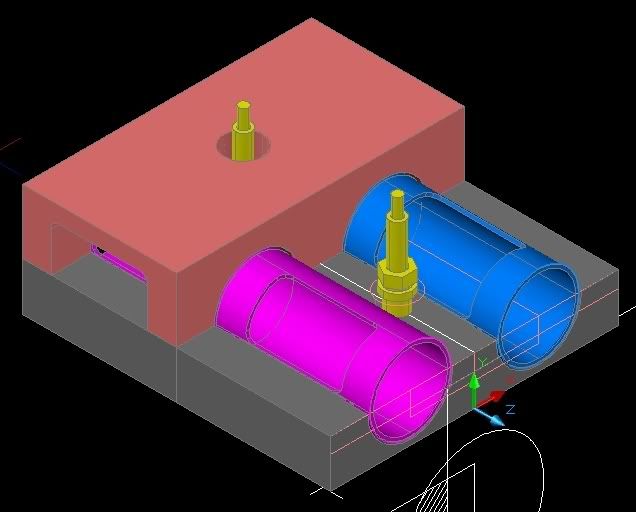
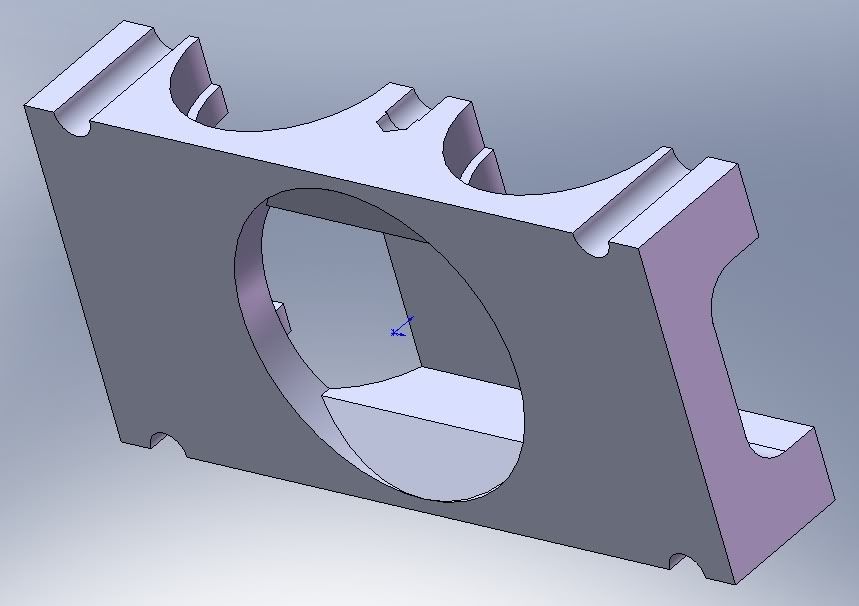
rotaryvalveman's combustion chamber design closely follows 2 stroke design, a double squish disk shape, with the addition of lozenge shaped ports.

I have a great deal of respect for Ralph Watson, especially as he designed and built by himself. Seeing his barn tool shop, this was no high tech effort, instead craftsmanship and engineering acuity, very old school, a lot to admire. Back in the 0's there was still a lot of garage projects. I remember several covered by Cycle World , a 500cc V8 using Honda 50 barrels and heads. A 250cc Ducati stretched to 350cc which inspired the factory to follow suit, in the 70's the 50cc GP class had a lot of garage enterprises, producing engines, I remeber a lot of aluminum monocoque chassis. It would be interesting to have access to Mr Watson's work. Reading through links, he had a life long involvement with aeroplanes, cars and boats, the articles impress that he was well regarded as a friend to those that helped commit his work to print. Passed away in 2006 at 94.

User avatar
flynfrog
Moderator
Joined: 23 Mar 2006, 22:31

Re: rotary valve technology

Post

rotaryvalveman wrote:previous post to F1 Eng.

In regards to cooling, there are some cooling ports in the pictures you see on mine and the head bolts were not a problem as you tightened the bottom half of the head up, put the rotors in place which covered the top of the bolts up and then closed the head by putting the top on the bottom of the head with bolt pattterns that did not interfere with anyrthing as we could put them where we wnated.

I am not sure why you would have such a problem packaging things except that I did not do this on my own. I had a small team of people to work with and if you did this on your own it might get a bit too much to try and come up with all the solutions. I know this was beyond me on my own and I had some good quality help from some good friends. Maybe that is the key.
are you saying those small radisued groves? How is this going to cool the combustion chamber?

Carlos
Carlos
11
Joined: 02 Sep 2006, 19:43
Location: Canada

Re: rotary valve technology

Post

Of interest - A development of the Belleville seal by John Crane Company, the performance figures seem about right:
Type LMPC - Live-Loaded Mechanical Packing Cartridge Seal
http://www.johncrane.com/iPortal/upload ... S_lmpc.pdf 4 pages
Temperature:
-268°C to 650°C / -450°F to 1200°F
! Pressure:
Pumps: vacuum to 68 bar g/1000 psig
Valves: 410 bar or 6025 psig
! Speed:
20 m/s / 3937 fpm

Question - Speed capability too low?

User avatar
rotaryvalveman
0
Joined: 24 Jun 2010, 11:46
Location: Brisbane

Re: rotary valve technology

Post

flynfrog, in answer to your question, we actually found that we had TOO MUCH cooling at one point, which was a bit of a shock. This was part of the learning curve. If you remember that the poppit valve has now gone, the poppit valve is one of the contributors to retaining heat. In a Rotary Wankel engine, for example, the exhaust temperature is over 1000 degrees whereas in a convventual engine, the poppit valve takes a great deal of the heat and flow out of the gasflow. That is why we needed less cooling than a conventual design. we only got everything to expand correctly after we REDUCED the cooling to the head.

there is general cooling of the head but the chamber is much much cooler, even after a couple of hours of running.

User avatar
rotaryvalveman
0
Joined: 24 Jun 2010, 11:46
Location: Brisbane

Re: rotary valve technology

Post

the johncrane company seem to have a great deal of sealing solutions but I will have to look closer at thier product line to see if it is appicable but I am pretty happy with the design and material list we already have. We will see but I have had a few years to think this one through. I will bear it in mind, however, if we are not as succesful as I think we are going to be in the long term trial.

User avatar
flynfrog
Moderator
Joined: 23 Mar 2006, 22:31

Re: rotary valve technology

Post

rotaryvalveman wrote:flynfrog, in answer to your question, we actually found that we had TOO MUCH cooling at one point, which was a bit of a shock. This was part of the learning curve. If you remember that the poppit valve has now gone, the poppit valve is one of the contributors to retaining heat. In a Rotary Wankel engine, for example, the exhaust temperature is over 1000 degrees whereas in a convventual engine, the poppit valve takes a great deal of the heat and flow out of the gasflow. That is why we needed less cooling than a conventual design. we only got everything to expand correctly after we REDUCED the cooling to the head.

there is general cooling of the head but the chamber is much much cooler, even after a couple of hours of running.

my two stroke engines require a lot of cooling to the combustion chamber and have no poppit valves how does your engine get rid of the heat. Also what engine are you using for a 450cc test

riff_raff
riff_raff
132
Joined: 24 Dec 2004, 10:18

Re: rotary valve technology

Post

rotaryvalveman,

I can tell by looking at the relative sizes of your ports and cylinder bore that your engine's flow will not be as good as a 4-valve poppet head. This will become clear if you do a port time-area analysis. The reason for this is that your valve's instantaneous flow area is always a sinusoidal function, while a poppet valve's is not limited to that motion. Even though the poppet valve's total port might be slightly less, it can achieve max flow quicker and for longer periods than your rotary valve. Compare the two and you'll see.

You will also have other issues, such as overheating of the aluminum port edges around the exhaust opening. These exhaust port edges are thermally isolated from the coolant flow, and experience the worst heat transfer combination of high exhaust gas flow velocities and temperatures right at exhaust valve opening. The corners will melt away and then crack due to thermal fatigue.

riff_raff
"Q: How do you make a small fortune in racing?
A: Start with a large one!"

F1_eng
F1_eng
4
Joined: 05 Aug 2009, 11:38

Re: rotary valve technology

Post

How do you come to the conclusion of a sinusoidal area function for the rotary valve?

tok-tokkie
tok-tokkie
38
Joined: 08 Jun 2009, 16:21
Location: Cape Town

Re: rotary valve technology

Post

Thanks for the link to Watson. Stacks to read there.

The bellville sprung John Crane mechanical seal is complex. Here is link to Wiki showing a generic simple mechanical seal http://en.wikipedia.org/wiki/End_face_mechanical_seal Some use a single spring as shown - others have many small springs somewhat like rollers in a roller bearing but each in its own pocket.
The seal on the exhaust side of the Watson engine was very much like a mechanical seal.

The sealing faces of a mechanical seal are usually ceramic on brass or graphite & are sold as replacement parts. They may be a convenient source for components for your project.

User avatar
rotaryvalveman
0
Joined: 24 Jun 2010, 11:46
Location: Brisbane

Re: rotary valve technology

Post

For the record, the airflow was so great in the original that we had to make it smaller and smaller.

As for the presumtion of sinusoidal, we have more flow from the moment the valve opens even if we peg the flow to the same peek level of the original. We filled in the gap that a poppit valve never could from the moment the valve is off the seat.

A few numbres. when we had a 1.8 litre 74mm bore four cylinder head mock up, we had 188CFM of airflow. The same engine in four-valve poppit form gave 75cfm off the factory floor and 136cfm after hours of porting and the biggest valves we could fit.

And even at this level, we had room to improve if needed. As for the cooling, I can only say what happened. It had too much cooling and responded better to less. Why I am not 100% sure but the retention of heat by the poppit valve is my logical analysis. I only base things now on fact. What I share is either based on this or I will say otherwise.