Exhaust Blown Floor - Forward Exhaust Exit

Here are our CFD links and discussions about aerodynamics, suspension, driver safety and tyres. Please stick to F1 on this forum.
User avatar
forty-two
0
Joined: 01 Mar 2010, 21:07

Re: Exhaust Blown Floor - Forward Exhaust Exit

Post

marcush. wrote:
forty-two wrote:Possibly true!

Actually, my biggest concerns are:
- Proximity of exhaust pipe to fuel cell.
- Danger for operatives during pitstops.

EDIT Thinking about it, most road cars route their exhaust under the fuel tank, but two important differences exist. Fuel tanks are metal, and exhaust doesn't run anything like as hot!
:lol: it seems you have not looked under a contemporary car for quite a while forty two....fuel tanks are ,without exception now made of:plastics. :shock:

as for the exhausts run to the front...they need some air channelled around the pipes running in the sidepods to isolate...or a water jacket (which would cool the flow and lead to a loss of energy maybe?)....both will increase necessary airflow through the sidepods and look at the quite big inlets...
I doubt you could just coat with thermal barrier and add a bit of wrap and get away with it.
No need to be snippy Marcus, perhaps my post was a little unclear, but I was referring to ROAD cars when I mentioned metal fuel tanks (the clue should've been the fact I said tank instead of cell!)

As for the cooling issue, perhaps that's the idea with the rectangular inlets beneath the drivers knees?
The answer to the ultimate question, of life, the Universe and ... Everything?

Michiba
4
Joined: 28 Apr 2008, 08:58

Re: Exhaust Blown Floor - Forward Exhaust Exit

Post

I mentioned it before, but this would be interesting reading:

viewtopic.php?f=1&t=7498&start=30

Part of the function of the exhaust there would be to mimic the effects of the now banned wheel fairings.

There was another post in another thread that even postulated that the air from the wheel fairings was directed to beneath the floor and exit the rear through the diffuser. I can't find the video but I remember it was in Italian. Perhaps someone can help me here.

marcush.
159
Joined: 09 Mar 2004, 16:55

Re: Exhaust Blown Floor - Forward Exhaust Exit

Post

forty two ,i was referring to road cars actually...simple cheap plastic ,harsh reality....I apologise for being snippy...

material of use is polypropylen -thermoplastics. sorry again for the offence..

vinuneuro
0
Joined: 04 Feb 2010, 19:34

Re: Exhaust Blown Floor - Forward Exhaust Exit

Post

I have to ask.. how is the exhaust flow contained under the floor over that distance in yaw?

User avatar
PlatinumZealot
550
Joined: 12 Jun 2008, 03:45

Re: Exhaust Blown Floor - Forward Exhaust Exit

Post

Good question, because this device is required to work in high speed turns.

Maybe the deflection of the gas stream in yaw is small. The car is moving on average 90mph(?) through the turns, the forward vector is large compared to angle of yaw.
🖐️✌️☝️👀👌✍️🐎🏆🙏

secretf1
0
Joined: 31 Jan 2011, 16:07

Re: Exhaust Blown Floor - Forward Exhaust Exit

Post

marcush. wrote:forty two ,i was referring to road cars actually...simple cheap plastic ,harsh reality....I apologise for being snippy...

material of use is polypropylen -thermoplastics. sorry again for the offence..
You are right in terms of the plastic fuel tanks on modern road vehicles. Simple and cheap I would not agree with, they are complex in terms of their structure and manufacturing process, and fairly expensive to a customer.

I could go into the reasons but it's off topic.

Back to fuel tanks in F1.

The rules state the following for fuel tanks:

ARTICLE 6: FUEL SYSTEM
6.1 Fuel tanks:
6.1.1 The fuel tank must be a single rubber bladder conforming to or exceeding the specifications of FIA/FT5-1999, the fitting of foam within the tank however is not mandatory. A list of approved materials may be found in the Appendix to these regulations.
6.1.2 All the fuel stored on board the car must be situated between the front face of the engine and the driver's back when viewed in lateral projection. When establishing the front face of the engine, no parts of the fuel, oil, water or electrical systems will be considered.
Furthermore, no fuel can be stored more than 300mm forward of the highest point at which the driver's back makes contact with his seat. However, a maximum of 2 litres of fuel may be kept outside the survival cell, but only that which is necessary for the normal running of the engine.
6.1.3 Fuel must not be stored more than 400mm from the longitudinal axis of the car.
6.1.4 All rubber bladders must be made by manufacturers recognised by the FIA. In order to obtain the agreement of the FIA, the manufacturer must prove the compliance of his product with the specifications approved by the FIA. These manufacturers must undertake to deliver to their customers exclusively tanks complying to the approved standards.
A list of approved manufacturers may be found in the Appendix to these regulations.
6.1.5 All rubber bladders shall be printed with the name of the manufacturer, the specifications to which the tank has been manufactured and the date of manufacture.
6.1.6 No rubber bladders shall be used more than 5 years after the date of manufacture.
6.2 Fittings and piping:
6.2.1 All apertures in the fuel tank must be closed by hatches or fittings which are secured to metallic or composite bolt rings bonded to the inside of the bladder. The total area of any such hatches or fittings which are in contact with the fuel may not exceed 30000mm².
Bolt hole edges must be no less than 5mm from the edge of the bolt ring, hatch or fitting.
6.2.2 All fuel lines between the fuel tank and the engine must have a self sealing breakaway valve. This valve must separate at less than 50% of the load required to break the fuel line fitting or to pull it out of the fuel tank.
6.2.3 No lines containing fuel may pass through the cockpit.
6.2.4 All lines must be fitted in such a way that any leakage cannot result in the accumulation of fuel in the cockpit.
6.3 Crushable structure:
The fuel tank must be completely surrounded by a crushable structure, which is an integral part of the survival cell and must be able to withstand the loads required by the tests in Articles 18.2.1 and 18.3.

There are some points in there with regard to construction, and also protection for the tank in a crash situation. I am sure Lotus Renault GP Ltd. have considered these in their design. I would also think that Charlie would have been consulted prior to the roll out of the car also.

secretf1
0
Joined: 31 Jan 2011, 16:07

Re: Exhaust Blown Floor - Forward Exhaust Exit

Post

In fact just looking into Articles 18.2.1 and 18.3, these tests appear to be completed on the survival cell and not the car assembly as a whole. So technically to the regulations the car I am sure is fine. A crash test would not be completed with the car assembly as a whole, however again I am sure it would be considered during design phase and Charlie would have been consulted.

User avatar
ringo
225
Joined: 29 Mar 2009, 10:57

Re: Exhaust Blown Floor - Forward Exhaust Exit

Post

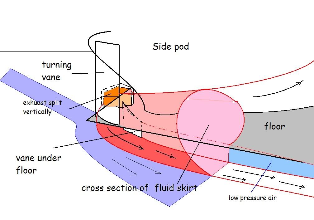
This was my idea,
Image
it may work, but i just realized something as well.

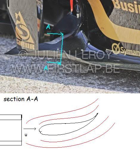
There's this:

cutting a section along the axis of the exhuast
Image

The mirror mount is an airfoil, basically like a rear wing. Worse it's like a wing in ground effect.
Exhaust velocity is very high, so you get the picture.

It's a really good idea. Brave end of the brave. It better be the fastest car on the grid. I would feel sorry for them if they weren't.
For Sure!!

marcush.
159
Joined: 09 Mar 2004, 16:55

Re: Exhaust Blown Floor - Forward Exhaust Exit

Post

I had this very same idea posted in the R31 thread...does two fools thinking the same create a truth? :mrgreen: (In that case it was one fool ...I cannot judge for your state of mind)
marcush. wrote:to me the thing looks like they are blowing the cup holders with the hot exhaust gas .These are airfoil shaped and in side view of the car you can even see how the profile forms a gurney -even if it´s longitudinally orientated.
With the exhaust blowing this wing section this generates downforce ,downforce close to the leading edge of the sidepod,near the CoG of the car this cannot be a bad thing even though ,admittedly the span of that wing is not big.

But what about the outer boundaries of this airflow? will it follow the undercut of the sidepods ?

If nothing else hot air is considerably less dense than cold air .So putting hot air into areas of positive lift or not usable for producing downforce due to their shape this could be used to reduce drag?

manchild
12
Joined: 03 Jun 2005, 10:54

Re: Renault R31

Post

I think that this will remain a secret until we see the car from below. I'm positive that at the front of floor there is at least one exit that does the virtual skirt effect, with another one on top jumping to aid by sealing the top of the floor's edge.
Last edited by manchild on 06 Feb 2011, 04:46, edited 1 time in total.

Giblet
5
Joined: 19 Mar 2007, 01:47
Location: Canada

Re: Exhaust Blown Floor - Forward Exhaust Exit

Post

Renault was using the exhaust a couple of years ago to attempt to heat the tires, but abandoned it.

If this is the configuration, then the tires are sure going to get some extra heat.

I bet Renault will be decent on restarts
Before I do anything I ask myself “Would an idiot do that?” And if the answer is yes, I do not do that thing. - Dwight Schrute

manchild
12
Joined: 03 Jun 2005, 10:54

Re: Renault R31

Post

Mystery solved, no more theories!

The exhaust pipe doesn't point forward but sideways, (even a bit to the back)

It has splitter within, and it is positioned so that exhaust gasses are split by the floor, so part of the them goes below the floor, part above = virtual skirts.

viewtopic.php?f=12&t=9187&start=431

Brightened and sharpened:

Image

Image

source:
http://www.f1fanatic.co.uk/wp-content/u ... LE0878.jpg
http://www.f1fanatic.co.uk/wp-content/u ... LE0965.jpg

Image

User avatar
humble sabot
27
Joined: 17 Feb 2007, 10:33

Re: Exhaust Blown Floor - Forward Exhaust Exit

Post

your graphics are correct manchild but i don't think your other assumption is. As you mentioned in the other thread, there's nothing you're allowed to do under the floor. That and the rules effectively forbid multiple exits as well.
@giblet, most of the heat will have dissipated by the time it reaches the tyres, if it were really that hot, there'd be more heat shielding in the front.

@ringo, i think you finally found something the rest of us hadn't seen. marcush.'s explanation is linguistically unintelligible so i'm discounting it :lol:
the four immutable forces:
static balance
dynamic balance
static imbalance
dynamic imbalance

n_anirudh
28
Joined: 25 Jul 2008, 02:43

Re: Renault R31

Post

...

From a very basic approach, I believe most of the exhaust would be sucked under the floor, rather than over it,
a) lower pressure under the floor.
b) a higher stagnation pressure over the sidepods and the floor leading edge.

However, some part would also flow over the top at low speed corners.

Correct me if I am wrong folks..
Last edited by mx_tifoso on 02 Feb 2011, 10:29, edited 1 time in total.
Reason: removed quoted post (manchild) since it appears almost right above.

bjpower
-1
Joined: 17 May 2009, 14:26

Re: Renault R31

Post

It looks to me that the exaust is going under the floor rther than over it.
maybe its just the angle

Post Reply