I may have worded it slightly confusingly/wrongly.
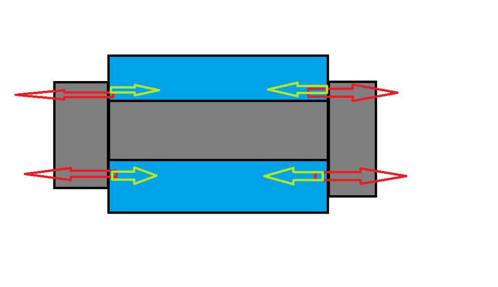
If you pre-load the bolt, the bolt will be stretched F/Kb
This same force is opposed by the con-rod which will stretch F/Kc
At TDC exhaust the inertia loads can be high, particularly for an F1 engine. The bolt does not have to deal with all this inertia load as a fluctuating load. The con-rod bolts would soon fail due to fatigue if it had to deal with total fluctuating load. This is all about fatigue, for anyone that didn't appreciate that.
The amount of fluctuating load that the bolt has to deal with is dependant on the stiffness ratio between the con-rod mating joint and the bolt. It is not a straightforward ratio though. The grooves are a method of tuning the joint stiffness to either increase of decrease the bolt alternating stress.
Formula None, the wasted shank is used to reduce the stiffness of the bolt which means the fluctuating stresses are less. This significantly improves the fatigue life of the bolt.
Very often if a con-rod bolt fails, people think you need to but a bigger bolt in or a stronger material. This would mean that the bolt would have to deal with a bigger portion of the fluctuating load. The worst case scenario is the joint separates and the bolt has to deal with the total fluctuating load, which could be assumed to be 80,000N split between two bolts.
On a simple M10 bolt, this would equate to a fluctuating tensile stress of approx 510MPa. You then need to use suitable stress concentration factors and look at the endurance limit or fatigue behaviour of the material. An alternating stress of 510MPa is quite high since the mean stress for the bolt is already usually pretty close to yield. The higher the mean stress, the less the allowable alternating stress. 510MPa around a 0 mean stress would be too high for most materials.
n smikle, I very much would like to get down to the details, what did you have in mind?
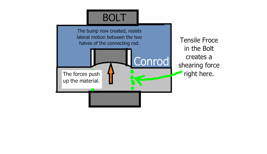
Do you know how to calculate the deflection of the simplified con-rod cap region shown in the image, assume the material is steel.
I may have worded it slightly confusingly/wrongly.
If you pre-load the bolt, the bolt will be stretched F/Kb
This same force is opposed by the con-rod which will stretch F/Kc
At TDC exhaust the inertia loads can be high, particularly for an F1 engine. The bolt does not have to deal with all this inertia load as a fluctuating load. The con-rod bolts would soon fail due to fatigue if it had to deal with total fluctuating load. This is all about fatigue, for anyone that didn't appreciate that.
The amount of fluctuating load that the bolt has to deal with is dependant on the stiffness ratio between the con-rod mating joint and the bolt. It is not a straightforward ratio though. The grooves are a method of tuning the joint stiffness to either increase of decrease the bolt alternating stress.
Formula None, the wasted shank is used to reduce the stiffness of the bolt which means the fluctuating stresses are less. This significantly improves the fatigue life of the bolt.
Very often if a con-rod bolt fails, people think you need to but a bigger bolt in or a stronger material. This would mean that the bolt would have to deal with a bigger portion of the fluctuating load. The worst case scenario is the joint separates and the bolt has to deal with the total fluctuating load, which could be assumed to be 80,000N split between two bolts.
On a simple M10 bolt, this would equate to a fluctuating tensile stress of approx 510MPa. You then need to use suitable stress concentration factors and look at the endurance limit or fatigue behaviour of the material. An alternating stress of 510MPa is quite high since the mean stress for the bolt is already usually pretty close to yield. The higher the mean stress, the less the allowable alternating stress. 510MPa around a 0 mean stress would be too high for most materials.
n smikle, I very much would like to get down to the details, what did you have in mind?
Do you know how to calculate the deflection of the simplified con-rod cap region shown in the image, assume the material is steel.
http://img812.imageshack.us/i/boltedjointexample.png/