F1 pankl conrod

All that has to do with the power train, gearbox, clutch, fuels and lubricants, etc. Generally the mechanical side of Formula One.
Post Reply
Jersey Tom
166
Joined: 29 May 2006, 20:49
Location: Huntersville, NC

Re: F1 pankl conrod

Post

Bolt science dot com... there is a website for everything.
Grip is a four letter word. All opinions are my own and not those of current or previous employers.

F1_eng
4
Joined: 05 Aug 2009, 11:38

Re: F1 pankl conrod

Post

n smikle, you can't afford to have any significant bending stress acting on the bolt. Bending is the designers worst nightmare, very large stresses can be induced by relatively small forces. As already said, the bolt is fairly close to yield when pre-loaded statically.
I don't know what your issue is, I have designed many of these bolted joints and not wildly over-engineered ones because the engineer does not understand exactly what is going on. If people such as yourself would rather I didn't say anything, all you have to do is ask. I thought you might have learned something.

Someone was asking about how to decide on bolt pre-load. You can either estimate or measure the loading which will be applied to the bolt dynamically. From this you know the force that will be trying to separate your bolted joint. Then you can decide on a safety factor and endurance limits and all that fatigue calculations. You can now make a decision on the bolt size and material etc.
Strictly speaking a bolt should be tightened to a specified deformation rather than a torque. If you know the bolt stiffness, you can work out the deformation required in the bolt to give you the required pre-load F=k.dx
The problem with a torque setting is as you mentioned, the pre-load force induced in the bolt is dependant on the lubrication of both the threads and bolt head. If the friction is very high, a large portion of the applied torque goes in just to overcome the friction under the head and threads. An extreme example is, say the friction was very high, you could end up reaching the specified torque setting to overcome friction but you have hardly deformed the bolt. It is this deformation of the bolt that gives the joint its pre-load. The friction is dependant on the axial force also so the friction force increases as pre-load increases.
That is a very brief introduction to a bolt pre-load, it gets a lot more involved when you actually want to start lifing a bolt for a working life, not over-engineer the bolt to be 10 times bigger than it needs to be.
Bolt stress is also very interesting, you have both shear and axial stress and because of the friction, shear stress plays a significant part. So tightening a bolt to 80% yield does not mean that the axial force induces 80% of the bolt yield stress, often the shear stress can be higher than the axial stress.

User avatar
PlatinumZealot
550
Joined: 12 Jun 2008, 03:45

Re: F1 pankl conrod

Post

On the bending. I am only telling you what I saw in the paper you posted. It actually can happen if you think of the geometry of the whole thing. It's not a matter of how you design it, Again it is what can happen in real life and the paper describes it.

Think about it on a very detailed scale.

Offset load will add a tensile force on the side of the near side of the Bolt and a compressive force to the far side of the bolt. If the flange material is stiffer the forces will be higher. This I suspect will be insignificant if the connecting rod halves are in contact as a said before, but I am going to investigate it none the less.

I am creating a model in solid works to test.
πŸ–οΈβœŒοΈβ˜οΈπŸ‘€πŸ‘ŒβœοΈπŸŽπŸ†πŸ™

riff_raff
132
Joined: 24 Dec 2004, 10:18

Re: F1 pankl conrod

Post

F1_eng,

While I may differ with your opinions on conrod bolt preloads vs. dynamic loads, I certainly agree with your comments regarding the total combined stress effects on the conrod bolt due to installation torques, and underhead flange bending due to dynamic loads. This is why conrod bolts are commonly tightened to a "stretch" value, instead of a wrenching torque.

The conrod cap is by nature a very poor structure for resisting bending between the bolts in relation to the magnitude of the inertia forces it is subject to. The end result of this structural arrangement is an inward angular deflection of the conrod cap and beam's thread axes. But with the cap and beam still being much stiffer in bending than the bolts themselves, the bolts end up taking all the bending stress.

Finally, from a pure structural efficiency standpoint, a conrod joint attachment that uses a bolt and nut would be a better choice than a conrod joint (like the Pankl rod shown) that uses a bolt and threaded hole in the beam. The bolt and threaded hole, however, is normally preferred for race engines due to its lighter weight and more compact size.

riff_raff
"Q: How do you make a small fortune in racing?
A: Start with a large one!"

User avatar
PlatinumZealot
550
Joined: 12 Jun 2008, 03:45

Re: F1 pankl conrod

Post

Riff-raff, how much radial force does the oil film push back on the big end bearing?
- because I want to model a connecting rod but I do not know what type of constraint I must set on the inside of the big end bore.
πŸ–οΈβœŒοΈβ˜οΈπŸ‘€πŸ‘ŒβœοΈπŸŽπŸ†πŸ™

riff_raff
132
Joined: 24 Dec 2004, 10:18

Re: F1 pankl conrod

Post

n smikle,

The conrod journal bearing hydrodynamic oil film must always react whatever the sum of the instantaneous radial forces acting through the crankpin is, by definition. Due to the kinematic degrees of freedom present at this journal bearing joint, it is subjected primarily to radial forces. It also can take some moments normal to the crank pin axis, since it has some axial face width in the bearing journal.

In a four-stroke engine, the instantaneous conrod bearing journal radial load vector constantly changes in magnitude and direction. The total area of the hydrodynamic oil film that supports the journal radial load can be quite small, but also of very high fluid pressures.

As for the loads acting on a conrod, once again you must consider the crank/conrod/piston mechanism's kinematic degrees of freedom. A conrod has similar joints at each end with 1 DOF in rotation and 1 DOF in translation. Thus it can only transmit force between the piston and crankpin in tension or compression, along a line that passes between the wrist pin and crankpin axes.

In practice, the conrod beam also is subjected to some bending, due to piston sliding frictions and mass inertias created by the rod swing.

As for accurately modeling the contact conditions present in a conrod journal bearing, that's a very complex situation due to its non-linearity. The only approach I could recommend for modeling such a contact condition with a linear FEM, would be to use some gap elements (like a "pbush" in PATRAN) that have high compressive stiffness, and very low stiffness in tension and rotations.

The peak oil film pressures in a journal bearing can be 20ksi or more. So you will need to define your load, and divide by area, with an assumed film pressure, to determine how large an area the journal load will be applied to on your conrod bore. The conrod loads should include inertias, combustion forces, and wrist pin and journal friction moments.

Hope that helps.
riff_raff
"Q: How do you make a small fortune in racing?
A: Start with a large one!"

nobeard
0
Joined: 31 Jan 2011, 14:55

Re: F1 pankl conrod

Post

Hi, can't tell you much about rods, but I have a couple of F1 rod picture somewere and will try to post them.

Conerning the bolt, they are not designed to fail after a certain number of cycles, they're designed not to fail under a number of cycles. If they are designed to fail in any way, it's the area where they fail, usually in the threads.

In high revolution engines most of the bolts are in nickel alloys, not in steel.

Again, in high rev engines bolts are thightened to their elastic limit in order to prevent movement from the rod's end. The elastic limit depends of the material and lubricant used. But again most of them are made in nickel alloys so the limit is very high.

cheers

User avatar
PlatinumZealot
550
Joined: 12 Jun 2008, 03:45

Re: F1 pankl conrod

Post

Tightened to the elastic limit, nobeard? I am not a bolt specialist but if those bolts go under any more tension they will go into the plastic zone. You are saying that is the intention?

I expect the addition of any more tension in that zone to cause sever extension so I don't think it would be good to do that. OR do you mean tightened until some of the bolt threads are on the elastic limit? You are talking about the threads or the bolt shank?

Image
πŸ–οΈβœŒοΈβ˜οΈπŸ‘€πŸ‘ŒβœοΈπŸŽπŸ†πŸ™

User avatar
mep
29
Joined: 11 Oct 2003, 15:48
Location: Germany

Re: F1 pankl conrod

Post

I dont think the bold is tightened to their elastic limit.
The joint should be designed in a way that the bold can take the additional force during operation and still having some safety factor up to the elastic limit.
The cut in the connection surface doesn't reduce the force on the bold.

F1_eng
4
Joined: 05 Aug 2009, 11:38

Re: F1 pankl conrod

Post

Right, people need to stop this. Engineering is solving problems using numerical skill.
mep, why do you say that the notch in the con-rod does not reduce the force in the bolt?
You will see from my previous posts why it does.

Go through the system, draw free body diagrams, balance forces etc.

So many half rate "engineers" that don't deserve to have an opinion. It is not difficult to see, approach it with an open mind.
Don't be scared that your first instinct might be wrong. There is no reason you should know how the bolt force changes dynamically, until you run the numbers. No-one is born knowing this stuff.
A lot of my first instincts are incorrect. I run the numbers and models myself before discussing them with people because you need numerical or experimental proof to back opinions up.
I could say, "don't be stupid, that notch doesn't change the bolt alternating load!". The engineer next to me could bring a sheet of paper out and show the calculations that prove it does. If I can't find an error in his calculation, it must be true. If I would have done the calculations myself before, I wouldn't have looked like an idiot in front of people which will stick in their mind.

If you are still having difficulty with understanding the bolt alternating force, I will derive the whole thing from start to finish if you want.
There are most probably books you could pick up to understand this.

Don't be afraid of learning new things, the best engineers are the ones that keep on learning.
I have a vast knowledge about a lot of things, but not everything.

User avatar
PlatinumZealot
550
Joined: 12 Jun 2008, 03:45

Re: F1 pankl conrod

Post

F1 eng, back on the bending load, we know bolts aren't designed to work under bending load. But the paper that YOU posted shows that the bolt can experience bending in some situations e.g during separation of two materials that are bolted together. It is something that actually happens.

Now at the same time, while I acknowledge that bolts can experience bending under flange separation, I do not think it applies to a connecting rod (I said that many times already) but I still want attempt a simulation to check if they are any loads that a reduced by adding the notch.

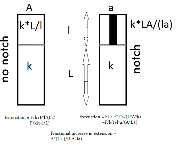
With that said, I do not expect the notch to reduce the axial load in the bolt under any conditions. Because the Cross sectional area of the notch and the elastic modulus of the connecting rod material does not change. The notch is only about 0.4mm deep, so I do not expect any great changes in stiffness in the axial direction. The material, titanium is already more pliant than the bolt so a 0.4mm notch would be insignificant reduction in stiffness in that direction.

I went on this "Bolt" tangent with you guys, and I listened to all the opinions 8) , but I still think the notch and the slanted cut is there to compress the outer hoop "fibres" of the connecting rod cap.

I am also open to the theory in the paper that you posted, so much so that I have a hunch that you can manipulate the theory of to show that, while there is no flange separation in a connecting rod, the reduction of stiffness in the radial direction caused by the notch can reduce bending inducing loads on the bolt. Think of like bending a plastic rod with a notch cut in it.
πŸ–οΈβœŒοΈβ˜οΈπŸ‘€πŸ‘ŒβœοΈπŸŽπŸ†πŸ™

nobeard
0
Joined: 31 Jan 2011, 14:55

Re: F1 pankl conrod

Post

Well there is a margin of security, obviously. Each team or engineer will decide what it is, might be 95% of the elastic limit for some, higher for others...
But the material allows for a tightening of this magnitude and the life of the assembly makes it possible too. This rod is most probably coming from an F1 engine, so we're talking 2500 km tops, less if it comes from an older version.

Cheers,

User avatar
PlatinumZealot
550
Joined: 12 Jun 2008, 03:45

Re: F1 pankl conrod

Post

I was asking you if you meant the stress approaches the yield in the shank of the bolt or the threads. Which one?
πŸ–οΈβœŒοΈβ˜οΈπŸ‘€πŸ‘ŒβœοΈπŸŽπŸ†πŸ™

riff_raff
132
Joined: 24 Dec 2004, 10:18

Re: F1 pankl conrod

Post

I made a quick FEM of the section of the rod cap in question, both with the groove and without it. The groove decreased compressive stiffness in the cap section under the bolt by about 11% in my simplified FEM. That's more than I would have expected, so it looks to be worthwhile if more elasticity in the clamped rod sections is desired.

I did a static analysis, and did not include friction in my boundary conditions. The simple axial load was applied over an annular area around the bolt hole, representative of the bolt head flange. I based the dimensions on what I could scale from BrianG's excellent photos.

riff_raff
"Q: How do you make a small fortune in racing?
A: Start with a large one!"

User avatar
PlatinumZealot
550
Joined: 12 Jun 2008, 03:45

Re: F1 pankl conrod

Post

So, the axial stiffness of the conrod clamped section is 11% lesser, hence there is higher threshold for separation. That is, the conrod cap will always stretch more than the bolt, "filling up" any gap that will form (as already said). So there is a benefit. Thanks riff_raff. is one numerically backed up point. =D>


Should be somewhat proportial to the reduction in CSA and the depth of cut.

Image

I made a small diagram.

ImageOk, that

This is all good, But what if the axial stiffness of the titanium conrod clamped section was already much lower than the bolt and there is already no separation without the notch? because a stifness dencrease of 11% over 0.4mm you can calulate using the above equations. extension change is gonna be small, but yes I agree it can be beneficial.

What I was interested in, if there is more to it, especially if it affects the shape of the bore, or the stiffness in the other direction changes as the rpm goes up, gonna try tonight one with no notch, one with a notch and a level mating surface and one with a notch with a slanted surface.
πŸ–οΈβœŒοΈβ˜οΈπŸ‘€πŸ‘ŒβœοΈπŸŽπŸ†πŸ™

Post Reply