Aspect Ratio and Stalling Angle
A stall occurs when the effective angle of attack reaches the critical angle. Induced downwash reduces the effective angle of attack of a wing. Since induced drag is inversely proportional to aspect ratio it follows that a low aspect ratio wing will have high induced drag, high induced downwash and a reduced effective angle of attack. The low aspect ratio wing therefore has a higher stalling angle of attack than a wing of high aspect ratio.
The reduced effective angle of attack of very low aspect ratio wings can delay the stall considerably. Some delta wings have no measurable stalling angle up to 40º or more inclination to the flight path. At this sort of angle the drag is so high that the flight path is usually inclined downwards at a steep angle to the horizontal. Apart from a rapid rate of descent, and possible loss of stability and control, such aircraft may have a shallow attitude to the horizon and this can be deceptive. The condition is called the super stall or deepstall, although the wing may be far from a true stall and still be generating appreciable lift.
Effect of Sweepback on Stalling
When a wing is swept back, the boundary layer tends to change direction and flow towards the tips. This outward drift is caused by the boundary layer encountering an adverse pressure gradient and flowing obliquely to it over the rear of the wing.
The pressure distribution on a swept wing is shown by isobars in Fig 8. The velocity of the flow has been shown by two components, one at right angles and one parallel to the isobars. Initially, when the boundary layer flows rearwards from the leading edge it moves towards a favourable pressure gradient, ie towards an area of lower pressure. Once past the lowest pressure however, the component at right angles to the isobars encounters an adverse pressure gradient and is reduced. The component parallel to the isobars is unaffected, thus the result is that the actual velocity is reduced (as it is over an unswept wing) and also directed outwards towards the tips.
Fig 8 Outflow of Boundary Layer

The direction of the flow continues to be changed until the component at right angles to the isobars is reduced to zero, whilst the parallel component, because of friction, is also slightly reduced. This results in a “pool” of slow moving air collecting at the tips.
The spanwise drift sets up a tendency towards tip stalling, since it thickens the boundary layer over the outer parts of the wing and makes it more susceptible to separation, bringing with it a sudden reduction in CLmax over the wing tips.
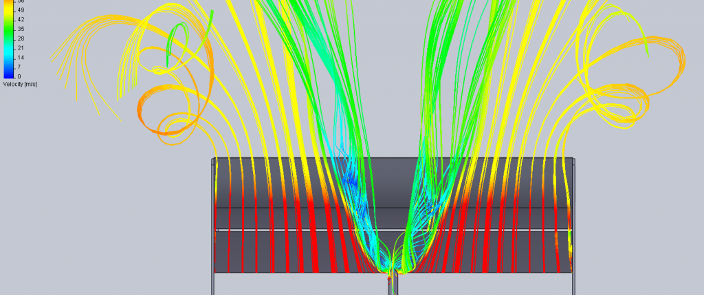
At the same time as the boundary layer is flowing towards the tips, at high angles of attack, the airflow is separating along the leading edge. Over the inboard section it re-attaches behind a short “separation bubble”, but on the outboard section it re-attaches only at the trailing edge or fails to attach at all. The separated flow at the tips combines with the normal wing tip vortices to form a large vortex (the ram’s horn vortex). The factors which combine to form this vortex are:
a. Leading edge separation.
b. The flow around the wing tips.
c. The spanwise flow of the boundary layer.
These factors are illustrated in Fig 9, and the sequence of the vortex development and its effect on the airflow over the wing is shown in Fig 10. From Fig 10 it can be seen that the ram’s horn vortex has its origin on the leading edge, possibly as far inboard as the wing root. The effect of the vortex on the air above it (the external flow) is to draw the latter down and behind the wing, deflecting it towards the fuselage (Fig 11).
Fig 9 Vortex Development

Fig 10 Formation of Ram’s Horn Vortex

Fig 11 lnfluence on External Flow

The spanwise flow of the boundary layer increases as angle of attack is increased. This causes the vortex to become detached from the leading edge closer inboard (see Fig 12). As a result, outboard ailerons suffer a marked decrease in response with increasing angle of attack. This, in turn, means that comparatively large aileron movements are necessary to manoeuvre the aircraft at low speeds; the aircraft response may be correspondingly sluggish. This effect may be countered by limiting the inboard encroachment of the vortex as described below, or by moving the ailerons inboard. Another possible solution is the use of an all-moving wing tip.
Fig 12 Shift of Ram’s Horn Vortex


