Sauber C32 Ferrari

A place to discuss the characteristics of the cars in Formula One, both current as well as historical. Laptimes, driver worshipping and team chatter do not belong here.
wesley123
wesley123
204
Joined: 23 Feb 2008, 17:55

Re: Sauber C32 Ferrari

Post

I think that mainly the enthausiasm about the solution, one of the very few this year, got the best of every one of us.

I do think the design has potential, but it looks like it is missing the downwash that other solutions has, and that gives a downside in getting the exhaust where it belongs.

Maybe Barcelona 2 might give us some clues on what is going on, but to be sure we'll have to wait and see how it performs in Australia
"Bite my shiny metal ass" - Bender

henra
henra
53
Joined: 11 Mar 2012, 19:34

Re: Sauber C32 Ferrari

Post

Owen.C93 wrote:Does make sense that these DRD systems are only powerful enough to blow the middle parts of the wings as seen by the Lotus flo vis. So they can be more aggressive in that area.
In an ideal world I would consider stalling the tips of the wing to be more efficient.
This would reduce induced drag as a nice side effect at the same amount of downforce loss.

That could be a benefit of a solution similar to the DDRS of Red Bull last year where the blew the Beam Wing from the end plates.

It is much harder to design though.

bhall
bhall
244
Joined: 28 Feb 2006, 21:26

Re: Sauber C32 Ferrari

Post

henra wrote:
Owen.C93 wrote:Does make sense that these DRD systems are only powerful enough to blow the middle parts of the wings as seen by the Lotus flo vis. So they can be more aggressive in that area.
In an ideal world I would consider stalling the tips of the wing to be more efficient.
This would reduce induced drag as a nice side effect at the same amount of downforce loss.

[...]
What if it actually does?

(Think of the convex underside of the Sauber wing every time you see a reference to either swept back wings or increasing angles of attack, and remember the location of the DRD jet in relation to the wing's leading and trailing edges.)
Aspect Ratio and Stalling Angle

A stall occurs when the effective angle of attack reaches the critical angle. Induced downwash reduces the effective angle of attack of a wing. Since induced drag is inversely proportional to aspect ratio it follows that a low aspect ratio wing will have high induced drag, high induced downwash and a reduced effective angle of attack. The low aspect ratio wing therefore has a higher stalling angle of attack than a wing of high aspect ratio.

The reduced effective angle of attack of very low aspect ratio wings can delay the stall considerably. Some delta wings have no measurable stalling angle up to 40º or more inclination to the flight path. At this sort of angle the drag is so high that the flight path is usually inclined downwards at a steep angle to the horizontal. Apart from a rapid rate of descent, and possible loss of stability and control, such aircraft may have a shallow attitude to the horizon and this can be deceptive. The condition is called the super stall or deepstall, although the wing may be far from a true stall and still be generating appreciable lift.

Effect of Sweepback on Stalling

When a wing is swept back, the boundary layer tends to change direction and flow towards the tips. This outward drift is caused by the boundary layer encountering an adverse pressure gradient and flowing obliquely to it over the rear of the wing.

The pressure distribution on a swept wing is shown by isobars in Fig 8. The velocity of the flow has been shown by two components, one at right angles and one parallel to the isobars. Initially, when the boundary layer flows rearwards from the leading edge it moves towards a favourable pressure gradient, ie towards an area of lower pressure. Once past the lowest pressure however, the component at right angles to the isobars encounters an adverse pressure gradient and is reduced. The component parallel to the isobars is unaffected, thus the result is that the actual velocity is reduced (as it is over an unswept wing) and also directed outwards towards the tips.

Fig 8 Outflow of Boundary Layer
Image

The direction of the flow continues to be changed until the component at right angles to the isobars is reduced to zero, whilst the parallel component, because of friction, is also slightly reduced. This results in a “pool” of slow moving air collecting at the tips.

The spanwise drift sets up a tendency towards tip stalling, since it thickens the boundary layer over the outer parts of the wing and makes it more susceptible to separation, bringing with it a sudden reduction in CLmax over the wing tips.

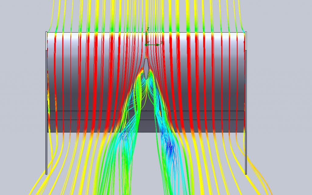
At the same time as the boundary layer is flowing towards the tips, at high angles of attack, the airflow is separating along the leading edge. Over the inboard section it re-attaches behind a short “separation bubble”, but on the outboard section it re-attaches only at the trailing edge or fails to attach at all. The separated flow at the tips combines with the normal wing tip vortices to form a large vortex (the ram’s horn vortex). The factors which combine to form this vortex are:

a. Leading edge separation.

b. The flow around the wing tips.

c. The spanwise flow of the boundary layer.

These factors are illustrated in Fig 9, and the sequence of the vortex development and its effect on the airflow over the wing is shown in Fig 10. From Fig 10 it can be seen that the ram’s horn vortex has its origin on the leading edge, possibly as far inboard as the wing root. The effect of the vortex on the air above it (the external flow) is to draw the latter down and behind the wing, deflecting it towards the fuselage (Fig 11).

Fig 9 Vortex Development
Image

Fig 10 Formation of Ram’s Horn Vortex
Image

Fig 11 lnfluence on External Flow
Image

The spanwise flow of the boundary layer increases as angle of attack is increased. This causes the vortex to become detached from the leading edge closer inboard (see Fig 12). As a result, outboard ailerons suffer a marked decrease in response with increasing angle of attack. This, in turn, means that comparatively large aileron movements are necessary to manoeuvre the aircraft at low speeds; the aircraft response may be correspondingly sluggish. This effect may be countered by limiting the inboard encroachment of the vortex as described below, or by moving the ailerons inboard. Another possible solution is the use of an all-moving wing tip.

Fig 12 Shift of Ram’s Horn Vortex
Image

stefan_
stefan_
696
Joined: 04 Feb 2012, 12:43
Location: Bucharest, Romania

Re: Sauber C32 Ferrari

Post

Matt Somerfield ‏@SomersF1

Sauber C32 Internal ducting that makes the path to DRD periscope. (via Sutton Images)

Image
"...and there, very much in flames, is Jacques Laffite's Ligier. That's obviously a turbo blaze, and of course, Laffite will be able to see that conflagration in his mirrors... he is coolly parking the car somewhere safe." Murray Walker, San Marino 1985

flyboy2160
flyboy2160
84
Joined: 25 Apr 2011, 17:05

Re: Sauber C32 Ferrari

Post

the analogy to an open tipped swept aircraft wing above isn't really valid because of the massive vertical end plates "sealing off" the ends of the F1 wings and, in almost all cases, the lack of any real sweep. the "tip" vortices must be dramaticaly affected by the end plates with their numerous little slits (and now slats in the case of the new ferrarri.) aircraft can use fences and snagged leading edges to help control that spanwise flow. the huge fenced in vertical supports on an F1 car must make them a unique case.

bhall
bhall
244
Joined: 28 Feb 2006, 21:26

Re: Sauber C32 Ferrari

Post

Swept wings are far from the only reason for spanwise flow. Admittedly, though, that does help, and it just so happens that if you follow the likely path of flow from the DRD jet...

Image
(Sometimes a different perspective helps.)

And here are two great reasons why a team might want to implement such a system.

Image
(via Scarbs)

User avatar
ringo
240
Joined: 29 Mar 2009, 10:57

Re: Sauber C32 Ferrari

Post

Blackout wrote:Matt Somerfield ‏@SomersF1
Sauber C32 - An even better shot of the internal pipework associated with DRD via @SuttonImages #TechF1 #F1 pic.twitter.com/hl6HbI96Ud

https://pbs.twimg.com/media/BDn1DM4CQAA_qYf.jpg:large
Sometimes i wonder if these devices reduce drag. It does stall part of the wing for sure.
But based on how it stalls the wing, i really wonder if there is a drag reduction.

back view
Image

angled
Image

beneath, looking up
Image

This is a preliminary test to see what's happening, so i don't have any data on it, whether it reduces drag or increases downforce. The car is moving at 55m/s and that trumpet thing is blowing at aroun 65m/s.
reality is we don't know if it's moving faster than free stream. I suspect is moving slower, but i just wanted to push things a bit to get an exageration of what is going on.

mods if there is a thread already in the aero section please move this post to it.
For Sure!!

User avatar
Artur Craft
40
Joined: 05 Feb 2010, 15:50

Re: Sauber C32 Ferrari

Post

Guys, this is quite an interesting issue that I had in my mind since I first saw Sauber's new rear wing. I wondered the effect of such central section

Forget about the DRD effect for a moment, Sauber was also using it even when not running the device's pipe

I asked one of the members(amouzouris, a great guy who have an awesome technical blog btw) to run CFD tests to see the efficiency of C32's new rear wing, the results are here:
http://www.f1technical.net/forum/viewto ... =6#p413338

The wing is less efficient, on itself, than a normal wing. In another words, it gives less downforce for the same drag and vice versa
Image
To bring some numbers, the old wing, the one without the curved central section, gives around 15% less drag, for the same downforce

Some CFD shots of both, just for curiosity:
A wing more like the old design
Image

A wing more like the new design
Image

Old like
Image

New like
Image
We must now look to where this is benefiting the overall car's performance, as obviously nobody would be using it if it wasn't benefitial in some way
Last edited by Artur Craft on 24 Feb 2013, 03:40, edited 1 time in total.

wesley123
wesley123
204
Joined: 23 Feb 2008, 17:55

Re: Sauber C32 Ferrari

Post

imo compared to the 2 wings shown the central section is much less deep than shown. Also it's leading edge has much less of this central spoon.
"Bite my shiny metal ass" - Bender

User avatar
Artur Craft
40
Joined: 05 Feb 2010, 15:50

Re: Sauber C32 Ferrari

Post

wesley123 wrote:imo compared to the 2 wings shown the central section is much less deep than shown. Also it's leading edge has much less of this central spoon.
Regardless of the magnitude of the spoon, it just shows the trend of the effect that such shape have

This spoon shape gives less L/D ratio

wesley123
wesley123
204
Joined: 23 Feb 2008, 17:55

Re: Sauber C32 Ferrari

Post

I am not so confident about that. The wings in the CFD miss a lot of details.

Apart from that, in the spoon in the CFD the 2 halfs meat at a really sharp angle, that cannot be good for aero.
"Bite my shiny metal ass" - Bender

bhall
bhall
244
Joined: 28 Feb 2006, 21:26

Re: Sauber C32 Ferrari

Post

Artur Craft wrote:Regardless of the magnitude of the spoon, it just shows the trend of the effect that such shape have

This spoon shape gives less L/D ratio
The lack of vents on the end plates skews the simulation considerably, particularly in the case of the "spoon" wing, which is a design that's been around for years as a lower-drag wing. Without vents to bleed off pressure, the pressure builds and builds and builds until it's finally shed as big, drag-inducing vortices.

Image
Last edited by bhall on 24 Feb 2013, 05:47, edited 1 time in total.

Owen.C93
Owen.C93
177
Joined: 24 Jul 2010, 17:52

Re: Sauber C32 Ferrari

Post

Also flow isn't consistent on the rear wing. The middle has the roll hoop and engine cover disrupting the flow. Something to consider.
Motorsport Graduate in search of team experience ;)

User avatar
hollus
Moderator
Joined: 29 Mar 2009, 01:21
Location: Copenhagen, Denmark

Re: Sauber C32 Ferrari

Post

The alignment is far from perfect, but Sauber's spoon wing does not have an extended center, it has a shallower profile at the end plates. The center is likely using the whole extension of the legality box, like any other team.
The shallower profile at the end plates likely can be compensated by less or smaller louvers.

Image
TANSTAAFL

shelly
shelly
136
Joined: 05 May 2009, 12:18

Re: Sauber C32 Ferrari

Post

Sauber has much smaller "ears". Also one curious thing is that lotus ears are not removable - they are glued to the chassis and are not formed by a removable bodywork panel like sauber's. So when lotus are not using drd, they are forced to run with closed ears, and maybe the small wing in the inlet is a correction for the aribox flow in that condition. I do not know why lotus have chosen to have "permanent" ears - it seems odd at first glance.
twitter: @armchair_aero