[KVRC] CCE LMP 2016

Post here information about your own engineering projects, including but not limited to building your own car or designing a virtual car through CAD.
User avatar
RicME85
52
Joined: 09 Feb 2012, 13:11
Location: Derby
Contact:

Re: [KVRC] CCE LMP 2016

Post

I wonder if the idea I had and tested last season for the front suspension might come into its own on the spec series (having the suspension members enclosed - I took the suspension travel template and offset it by 10mm to give it thickness) this would obviously mean the front suspension cannot be seen but airflow can pass through it.

Green is the supplied template for suspension.

Image

Image

You can see the slight size increase between the template and the cover I came up with.

User avatar
machin
162
Joined: 25 Nov 2008, 14:45

Re: [KVRC] CCE LMP 2016

Post

I think the suspension elements themselves are pretty low drag (small frontal area, tear-drop shape), so my concept is to leave them alone and to keep the bodywork as far away as possible to reduce the amount of "blockage" in that area.... Below is a section through the car as it was tested:-

Image

The plan now is to change the leading edge of the upper suspension cover to (hopefully) encourage more air through that area.....

Whilst I'm doing sections... here is a section through the rear of my car:-

Image

and here is the downforce distribution:-

Image

The diffuser is working OK, but last year the good cars were peaking at over 400N of downforce in the diffuser, whereas mine is only just over 300N.... The next step is to look at the CFD results in detail and try and figure out what I need to do to improve that (I tried a few days ago and got an error trying to load the foam file, so will need to have a look into that... is it because I am using too recent a version of Paraview? I don't know but I'll look into that....)
COMPETITION CAR ENGINEERING -Home of VIRTUAL STOPWATCH

User avatar
CAEdevice
45
Joined: 09 Jan 2014, 15:33
Location: Erba, Italy
Contact:

Re: [KVRC] CCE LMP 2016

Post

The suspensions elements would be low drag if they were aligned with the flow direction, that is not horizontal (parallel to the ground) in that area. The same happens with my car: consider that I lose about 500N (50% front 50% rear, in your case don't cobsidwr the effect on the rear axle, since the suspension is covered) of df and I gain 100N of drag in comparision with an ideal geometry with negligible suspensions effects.

It would help to have the possibility to add material around the suspensions beams.
Last edited by CAEdevice on 31 Mar 2016, 23:04, edited 2 times in total.

User avatar
CAEdevice
45
Joined: 09 Jan 2014, 15:33
Location: Erba, Italy
Contact:

Re: [KVRC] CCE LMP 2016

Post

Is the angle of attack of the diffuser larger than 30°? Do you have any method to define it during design? In my case it is a purely empirical process...

User avatar
variante
131
Joined: 09 Apr 2012, 11:36
Location: Monza

Re: [KVRC] CCE LMP 2016

Post

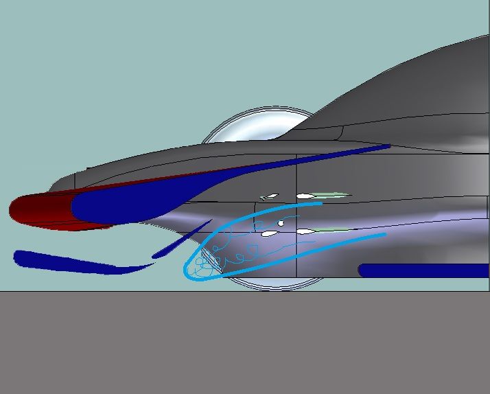
I had some fun trying to imagine what the airflow could look like with such a layout. Now, notice that i'm not saying that the following does happen to your car...i'm saying that they could happen, that there's a risk.
Image
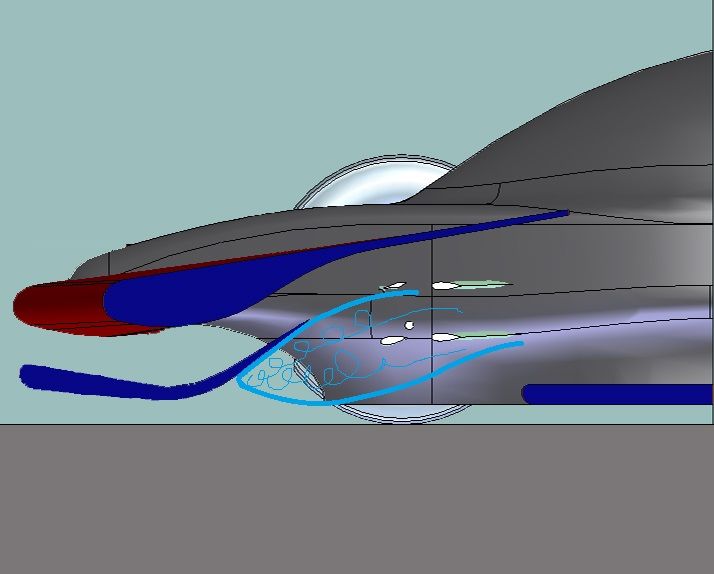
The transition zone into turbulent, which always appears with high angles of attack, could negatively involve the surface of the wing itself, decreasing its extraction capacity, thus downforce.
A gap feeding the rear part of the wing could solve this problem: the transition zone would still be there (as i said, it's quite inevitable with high downforce wings), but its entity would be decreased and the wing surface wouldn't be affected.
Image

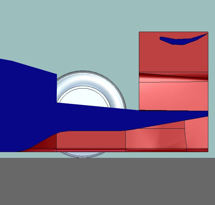
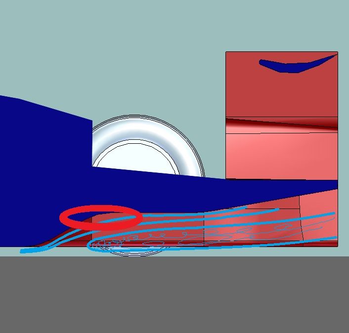
About the rear end of the car, as CAEdevice said, that diffuser is quite dramatic. I imagined two situations, shown in the following pics.
In the first one the flow doesn't separate, but after going through the first throat, it meets a "wall" where the pressure builds up (in the red circle). That transition could be more gentle. That thing may also cause the problem shown in the the other pic...
Image
...in fact, that steep expansion followed by the previously cited "wall" could lead to a recirculation zone, which would de facto decrease the expansion area much below its potential maximum.
Image
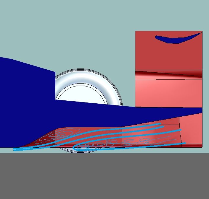
As always, vortex generators could make our life easier...

Last two considerations:
-front suspensions cover upwashes quite considerably: this helps front downforce but decreases the rear. In my tests, with my car, the total downforce balance was negative with this kind of solution.
-(this one is obvious...) the rear wing should be imported with more points :D

User avatar
CAEdevice
45
Joined: 09 Jan 2014, 15:33
Location: Erba, Italy
Contact:

Re: [KVRC] CCE LMP 2016

Post

This topic summarises the reasons I take part to the KVRC :) Thanks to Machin and to Variante.

Some other considerations from my point of view:

1) Wich is exactly the rear diff. starting angle? I have found a precise value for that angle with a raw optimization and this is the same value the I have found in some literature (I can say that it is above 20°). I can' t give it a physical meaning, isn't that value so big to cause flow detachment?

2) Vortex generators: it has been two years that I trying to manage small vortices (<50mm) but I could not obtain nothing. On the contray my rear diff is based on two big vortices (100mm), and in the future the front wing will worknin the same way. Maybe it depends on the mesh? A finer mesh would help?

3) Machin's car seems to have the typical "effciency" setup. Things would be very different with a full df setup. Personally I prefer the design of an efficient car, I hate the winglets I had to add to my original geometry...

User avatar
machin
162
Joined: 25 Nov 2008, 14:45

Re: [KVRC] CCE LMP 2016

Post

Unfortunately I haven't yet been able to load my FOAM file so I can't see what is actually going on, but I do suspect the diffuser is too steep... All the working surfaces are geometrically defined so that incremental adjustment is easy: the initial ramp of the rear diffuser was 30 degrees exactly on the test car.

I've already made my amendments to the car for the first official round and I can say that the modified front end looks a bit more similar to what Variante has drawn above... Plus a few little winglets/dive planes to try and get front balance.... I've dropped the diffuser ramp angle and increased the radius at the "kink line".... And naturally I've added a dual element rear wing.

Rest assured that the wing profiles do not have facets like they appear in that screenshot!!!
COMPETITION CAR ENGINEERING -Home of VIRTUAL STOPWATCH

wesley123
204
Joined: 23 Feb 2008, 17:55

Re: [KVRC] CCE LMP 2016

Post

The panel covering the suspension arms could hamper front downforce a bit as well. I'm thinking LMPs here and those cars are limited in front end aero because those panels act like a ceiling.
"Bite my shiny metal ass" - Bender

User avatar
machin
162
Joined: 25 Nov 2008, 14:45

Re: [KVRC] CCE LMP 2016

Post

Indeed: the front suspension has to be covered when viewed from the top and front as per the KVRC rules, just like the real LMP cars. It is one of the big challenges as it is very easy to design a low drag suspension cover which creates a lot of lift!
COMPETITION CAR ENGINEERING -Home of VIRTUAL STOPWATCH

User avatar
machin
162
Joined: 25 Nov 2008, 14:45

Re: [KVRC] CCE LMP 2016

Post

Well, fifth place in the KVRC test round was more than I could have hoped considering I purposely entered a low downforce car at a high downforce track: showing the importance of trying to make sure you have the full engine power available! Of course, this means that some of the other cars should be able to leap-frog my results when/if they sort out their cooling flow.

In the meantime I have created a basic bodykit for the benefit of other competitors who have not yet submitted a car and are struggling to do the CAD modelling. This model (yellow part in image below) is a modified version of my test car introductory class bodykit (adjusted to sort out two minor rules infractions), with the wings and diffuser removed.

A second file is included in the ZIP file which is a set of flat guide parts (light grey in the image below), which can be imported into Sketchup and used to easily extrude the wings and diffusers. These guide parts fit "inside" the main CCE bodykit (yellow) and the KVRC supplied parts (dark grey), and are therefore not visible in the complete car. There are four main guide parts:-
  • Front wing guides: extrude your wings between these parts.
  • Running plates: extrude any barge boards up from these.
  • Diffuser: extrude your diffuser shape between the two sides.
  • Rear Wing guides: extrude your wings between these end plates
Image

The two parts can be downloaded here:-

http://www.competition-car-engineering. ... odykit.zip

I don't recommend importing the main CCE bodykit part (yellow) into Sketchup because Sketchup makes a mess of it, so just submit this part as it is. (You could import it to have a look at it compared to your wings, but I definitely wouldn't re-save it)

Happy modelling!
COMPETITION CAR ENGINEERING -Home of VIRTUAL STOPWATCH

User avatar
CAEdevice
45
Joined: 09 Jan 2014, 15:33
Location: Erba, Italy
Contact:

Re: [KVRC] CCE LMP 2016

Post

machin wrote:In the meantime I have created a basic bodykit for the benefit of other competitors who have not yet submitted a car and are struggling to do the CAD modelling.
Great idea. I will do the same as soon as possible: there will be a "customer" release of CAEdevice car.