2 stroke thread (with occasional F1 relevance!)

All that has to do with the power train, gearbox, clutch, fuels and lubricants, etc. Generally the mechanical side of Formula One.
manolis
107
Joined: 18 Mar 2014, 10:00

Re: 2 stroke thread (with occasional F1 relevance!)

Post

Hello Pinger.

You write:
“..... and now ponder how to emulate a scooter CVT transmitting circa 5lbs.ft of torque with a 200lb cyclist generating 100lbs.ft torque without the belt slipping. Manipulate the force required for that from the handlebar? It'd be worse than tensioning a truck's fan belt - while simultaneously riding a bike.”


I don’t know what you mean by “tensioning a truck's fan belt”.

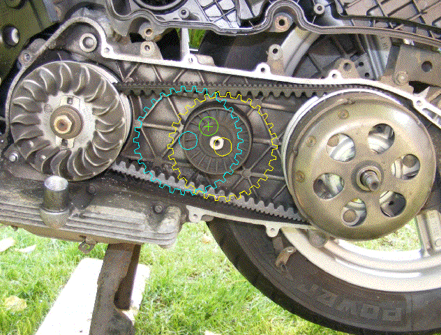
So, let’s make a rough calculation to find out how hard it is to shift to another gear ratio with the lever of the PatBox in a bicycle.


Suppose the coefficient of friction between the elastic V-belt and the conical pulley halves equals to 1.

Suppose a 100Kp (220lb) bicycler weight.

Suppose a 150mm (0.5ft) pedal crank-arm.

Suppose a 75mm (0.25ft) maximum radius of the V-belt running on the rear pulley, and a 1:1 minimum transmission ratio.

150mm/75mm=2

So, the rear pulley, at the shortest gear ratio (i.e. at the ratio the bicycle starts moving), has to apply a force of 2*100=200Kp (440lb) on the V-belt, so it is required a clamping force of 100Kp (220lb); (because force is applied on both sides of the V-belt).

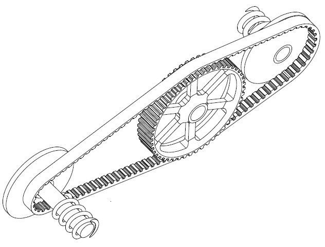
In order the auxiliary belt to displace the V-belt deeper in the rear pulley, it is required to apply to the V-belt a force of 100/4=25Kp (55lb): this is due to the wedge effect and to the angle of the conical pulley halves (say 28 degrees, tan(28/2)=0.25=1/4).

The auxiliary belt has two spans, one above and another below the V-belt. So, each span of the auxiliary belt has to be loaded by a force of 25/2=12.5Kp (28lb).

This is the force the movable roller-tensioner has to apply to the auxiliary belt horizontally.

Image

The handle (the top) of the lever is at a 3.5:1, or so, “leverage” relative to the upper roller-tensioner, which means, the hand of the bicycler has to apply on the lever a force of 12.5/3.5 = 3.5Kp (8lb), i.e. as much as a lightweight domestic cat weighs (from the Internet: according to APOP, a domestic cat should be about 8-10 lbs (3.6-4.5 kg)).


The previous rough calculations give an idea for the magnitude of the required force on the lever.
And it seems OK not only for the average bicycler, but also for the extra lightweight bicyclers.


The arrangement of the PatBox lever may seem strange and unconventional to the familiar with the derailleur / IGH / NuVinci bicycle gear-trains and control.

However for the new bicyclers, and for the bicyclers who dislike, or never got how to use efficiently, the conventional bicycle gear-train and control, the lever of the PatBox appears quite more physical and simple and understandable.


The following instructions for the use of the PatBox:

“When your legs are pedaling too fast push the lever forwards, and when your legs are pedaling too slow pull the lever backwards.”

is all a bicycler needs to know.

Thanks
Manolis Pattakos

J.A.W.
109
Joined: 01 Sep 2014, 05:10
Location: Altair IV.

Re: 2 stroke thread (with occasional F1 relevance!)

Post

Hi Manolis..

Back on topic with 2T tech, but still of interest, with a - 'twisted' - belt drive, rotary-valve set-up..

https://www.youtube.com/watch?v=7Ffs1x145zw
"Well, we knocked the bastard off!"

Ed Hilary on being 1st to top Mt Everest,
(& 1st to do a surface traverse across Antarctica,
in good Kiwi style - riding a Massey Ferguson farm
tractor - with a few extemporised mod's to hack the task).

manolis
107
Joined: 18 Mar 2014, 10:00

Re: 2 stroke thread (with occasional F1 relevance!)

Post

Hello J.A.W.

The diameter of the rotary valve seems quite big (200mm?) for the size of the engine.

And the diameter of the sprockets whereon the twisted tooth belt runs, seems too small (on the other hand, in case the toothed belt fails, the engine just stalls).

It seems he is trying to achieve both: bigger intake port area and faster opening - closing.
Maybe he is also trying to avoid the limitations from the reed valve.

The next reasonable step for the optimization of the intake in a wide rev range? A phaser.


By the way, the following "animation" shows a phaser (like those used for the timing of the camshafts of the 4-stroke engines) disposed between the crankshaft and the bevel gear that drives the rotary valve of the PatATE:

Image

Depending on the operational conditions, the controllable timing can give bigger share of the hybrid port time area to the exhaust, or to the transfer.

It can also optimize the intake (at lower revs the intake port should close earlier, at higher revs the intake port should close later).

Thanks
Manolis Pattakos

manolis
107
Joined: 18 Mar 2014, 10:00

Re: 2 stroke thread (with occasional F1 relevance!)

Post

Hello all.


PatCVT

In the PatCVT a sprocket or gearwheel (actually an idler) is intermeshed with "teeth" on both spans of the V-belt.
The displacement of the center of the sprocket varies positively the transmission ratio:

Image

enabling various "modes" of operation:

Drive Mode:
The lever that holds the sprocket is released to pivot freely about the cross; the CVT runs automatically under the control of a variator in the one conical pulley and of a spring / torque cam in the other conical pulley.

Sport Mode:
Performance oriented.
A control spring pushes the lever towards the conical pulley with the spring / torque cam; the CVT continues to run "fully automatic", but it selects shorter transmission ratios.

Economy Mode:
For green, quiet, reliable, comfortable operation.
The control spring pushes the lever towards the variator's conical pulley; the CVT continues to run "fully automatic" (as in the "Drive Mode"), but it selects longer transmission ratios.

Manual Mode:
The rider / driver displaces "manually" the lever about the cross to select any transmission ratio from the available infinity, regardless of what the "variator / spring / torque cam" command.
By locking the lever at a number of discrete positions, the CVT replicates a manual gear box.


In all modes the sprocket acts as a "baffle roller" (drive belt tensioner), too.

The available space inside the CVT of many scooters (like, for instance, the Sport-City Aprilia 250cc, below) is more than what the PatCVT needs:

Image


How it works?

With the sprocket engaged with the toothed-V-belt as in the animation, the sprocket divides the V-belt in two parts (one at left of the sprocket and another at right of the sprocket), with each part maintaining its length constant.

The move away of the center of the sprocket from the one conical pulley causes the decrease of the effective diameter the V-belt is running on this conical pulley, and the increase of the effective diameter the V-belt is running on the other conical pulley.


For more: http://www.pattakon.com/pattakonPatCVT.htm


Thoughts?

Thanks
Manolis Pattakos

Tommy Cookers
617
Joined: 17 Feb 2012, 16:55

Re: 2 stroke thread (with occasional F1 relevance!)

Post

at this moment I seem to need convincing that the argument below is incorrect (and how/why it is incorrect) .......

in the PatBox the controlling belt has rather small losses (that might be smaller again if it was eg a metal band)
in the PatCVT the controlling belt has loads passing through its teeth via the pulley teeth ? (the belt teeth you have said before are not intended for loads)
because the belt load path on the other side of the control point is 'length-compliant' (not rigid as in the PatBox)

so the controlling losses seem to be higher in the PatCVT

what can the PatCVT do that couldn't be done by controlling belt effective length/tension with an external tensioner ? (eg roller on back side of belt)
ie is its benefit entirely its compact latout ?

and the question (of whether losses are greater than in conventional systems of external CVT control) is still open ?

it might be argued that the Pat CVT is an enabler of the 2 stroke 'daily driver'

manolis
107
Joined: 18 Mar 2014, 10:00

Re: 2 stroke thread (with occasional F1 relevance!)

Post

Hello Tommy Cookers.

You write:
“in the PatCVT the controlling belt has loads passing through its teeth via the pulley teeth ? (the belt teeth you have said before are not intended for loads)
because the belt load path on the other side of the control point is 'length-compliant' (not rigid as in the PatBox)”


In the PatCVT there is no “controlling belt”.
There is only one belt, the V-belt, that has teeth at its inner side.

Image

The controller is the sprocket intermeshed with teeth on both spans of the V-belt.


Regarding the efficiency:

Take a scooter CVT, like, say, the SprotCity Aprilia 250cc of the photo, modified to PatCVT.

If you release the lever that holds the controlling sprocket, the bearing of the sprocket runs, more or less, unloaded; the teeth of the sprocket remain unloaded, too.
The sprocket acts as the original “baffle” roller.
The efficiency of the CVT is as without the PatCVT.

Now suppose that at some conditions you prefer a 15% shorter, or longer, transmission ratio than the ratio the CVT selects normally at these conditions.
The bearing of the sprocket and its teeth are far from being overloaded, because the sprocket has to apply to the V-belt only the difference of the force required for the specific transmission ratio, and because the efficiency of a toothed sprocket cooperating with a toothed belt is quite high (above 99%; worth to note: there is only one sprocket).

For instance, suppose a force of 20Kp (44lb) is applied on the center of the sprocket towards the one conical pulley; this force changes by 10Kp (22lb) the force acting on each span of the V-belt; and due to the wedge action of the conical pulley, this force (the 20Kp / 44lb) is multiplied by 4 to give the additional axial force resulting on the moving half of each conical pulley.
So, with 20Kp loading the roller bearing of the sprocket, and 10Kp force from the sprocket on each span of the V-belt, the axial force on the movable halve of each conical pulleys change by 80Kp (176 lb).

If something of the previous is confusing, please let me know to further explain.


You also write:
“what can the PatCVT do that couldn't be done by controlling belt effective length/tension with an external tensioner ? (eg roller on back side of belt)
ie is its benefit entirely its compact latout ?”

Any drawing?
I can’t get what you mean.

Thanks
Manolis Pattakos

Tommy Cookers
617
Joined: 17 Feb 2012, 16:55

Re: 2 stroke thread (with occasional F1 relevance!)

Post

you say .....
'the sprocket has to apply to the V belt only the difference in the forces'

I think losses will be produced by belt/sprocket action associated with each of the forces
ie proportionate to the algebraic sum of the forces not the difference in forces

manolis
107
Joined: 18 Mar 2014, 10:00

Re: 2 stroke thread (with occasional F1 relevance!)

Post

Hello Tommy Cookers.

You write:
“I think losses will be produced by belt/sprocket action associated with each of the forces
ie proportionate to the algebraic sum of the forces not the difference in forces”


Let’s take the marginal case wherein the lever of the sprocket is released to move freely.

The force between the sprocket and each span of the V-belt is near zero.
The force on the bearing of the sprocket is small, too.
These make the losses “produced by the belt/sprocket action” actually zero.

Obviously the strong force that loads the V-belt (through this force the one conical pulley transmits power to the other conical pulley) does not affect the above, almost zero, friction losses.

Do I miss something?

Thanks
Manolis Pattakos

Tommy Cookers
617
Joined: 17 Feb 2012, 16:55

Re: 2 stroke thread (with occasional F1 relevance!)

Post

since you ask, I find myself saying that you are missing a response to my point
and you are pre-emptively trivialising the loss aspect of the forces developed at the belt/control pulley contact region

however I wish your designs success in their widening of the scope of inexpensive properly controlled CVTs

Muniix
14
Joined: 29 Nov 2016, 13:29
Location: Sydney, Australia

Re: 2 stroke thread (with occasional F1 relevance!)

Post

uniflow wrote:
03 Aug 2017, 22:30
I say again manolis, make one and show us. pretty pictures mean nothing.
Watch out, you'll get your posts deleted, but the credibility you gain from the likes of the designer of the McLaren P1, Engineers from Audi, FCA, BMW, ... is worth it.

Muniix
14
Joined: 29 Nov 2016, 13:29
Location: Sydney, Australia

Re: 2 stroke thread (with occasional F1 relevance!)

Post

The crankshaft rotating assembly in the PATop design has excessive bearing friction and inertial forces due to having bigger big end diameter than main journals.

You don't need to perform a bearing friction model simulation to realise this.

You have excessive mass in the bigends meaning the smaller mains are under greater loads than they need be. Flexing the crankshaft more than it need to.

This is just bad engineering, what goal is this design trying to achieve, technical analysis only arrives at short man syndrome.

When someone does identify an issue it's never acknowledged or worse the classic deflection, straw man response follows. With the identified issue ignored and the original claim repeated all over the interwebs, confirming the analysis is correct, SMS.
manolis wrote:
04 Aug 2017, 07:39
Hello Uniflow.


You write:
“I say again manolis, make one and show us. pretty pictures mean nothing.”


However,
the meaning of a technical discussion like this one,
is by far different than:
“make one and show us”.


Someone proposes a new (or “new”) technical solution; the rest forum members can read, understand (the “pretty pictures” mean a lot in this stage) and think.

Then, if they like so, they write down their justified (or not) technical objections / thoughts.

It is a “win-win” process.


The guy who proposes the new, or “new”, technical solution is asking for “independent third party” objections and opinions in order to decide either to abandon the idea, or to proceed with it (by making prototypes, by testing them etc).

He is also presenting his idea to “whom it may concern”.


By the way:

Seven months ago, at page 87, posts #1296-1297, a discussion remained unfinished, even if the “make one and show us” was the case:


The PatOP pattakon engine is real:

http://www.pattakon.com/patop/PatOP1_mov.jpg

from metal:

http://www.pattakon.com/patop/PatOPpro6.jpg

http://www.pattakon.com/patop/PatOPpro2.jpg

works on Diesel fuel:

(youtube video: https://www.youtube.com/watch?v=2ByEgfTTq1I )

and concentrates unique characteristics:

Bore: 79.5mm
Stroke: 64+64=128mm
Displacement: 635cc
Compression ratio: 17
Scavenging pump bore: 130mm (1.34 scavenging ratio)
Total engine height: 500mm
Total engine weight (without the flywheel): less than 20Kp

It is an:
opposed-piston,
two-stroke,
single-cylinder,
single-crankshaft,
full-balanced (vibration free),
cross-head,
direct-injection Diesel engine,
with built-in "volumetric" (for a wider rev range and flat torque curve) scavenging pump,
with four-stroke-like lubrication,
and with some 35% as compared to the conventional, or some 20% as compared to the Junkers-Doxford and to the OPOC of EcoMotors, additional time for the injection and combustion of the fuel.


It is also patented,
which means that some experts / specialists in the field (examiners in big patent offices like the USPTO, the UK-IPO etc), after searching all the prior art, they decided the idea in question is new, it has inventive step and is industrially applicable.


Worth to mention here:

The only things from the market used in the above PatOP prototype engine are the piston rings (from a VW TDi), the plain bearings (from a BMW 1600cc) and the fuel injection system (it is from a cheap Chinese 4-stroke electric generator).
All the rest parts were made either from 7075 aluminum billet (if I remember correctly, we started with 54Kg (120lb) aluminum for the casing) or from Orvar Supreme steel (crankshaft, connecting rods).


Enjoy how nice, smoothly and clearly it runs on Diesel fuel, standing free on a desk. We talk for big single-cylinder direct injection Diesel engine.

The prototype works as the theory predicts.

However, the important is the theory, the theoretical solution proposed; not the working prototype.

Please do read, at the page 107, post #1601 of this thread, what the professor Rui Chen of the famous Loughborough University - UK did (“Quasi-constant volume spark ignition combustion”, presentation in the International Engine Expo 2009, Stuttgart Germany) in order to achieve the longer piston dwell of the OPRE and PatOP engines.


So, if you still don’t like to comment on the PatATE idea because the “make one and show us” requirement is not yet fulfilled,
you can alternatively write your technical objections / thoughts about the PatOP.

Thanks
Manolis Pattakos

gruntguru
563
Joined: 21 Feb 2009, 07:43

Re: 2 stroke thread (with occasional F1 relevance!)

Post

Muniix wrote:
22 Aug 2017, 04:57
The crankshaft rotating assembly in the PATop design has excessive bearing friction and inertial forces due to having bigger big end diameter than main journals.

You don't need to perform a bearing friction model simulation to realise this.

You have excessive mass in the bigends meaning the smaller mains are under greater loads than they need be. Flexing the crankshaft more than it need to.

This is just bad engineering, what goal is this design trying to achieve, technical analysis only arrives at short man syndrome.

When someone does identify an issue it's never acknowledged or worse the classic deflection, straw man response follows. With the identified issue ignored and the original claim repeated all over the interwebs, confirming the analysis is correct, SMS.
Muniix, sometimes you demonstrate a high level of understanding of engine technology but you repeatedly cancel such moments with one-eyed posts like this.

- Bearing friction? Seriously? Take a look at the OPOC.http://thekneeslider.com/ecomotors-team ... oc-engine/
Do you have any idea of the contribution of crankshaft bearing friction to engine losses? 100% increase in big end bearing friction would make a tiny difference - easy to justify if there are significant gains elsewhere.

- Main bearing loading? Seriously? The Pat OP has zero loading of the the main bearings - from combustion forces and inertial forces. They all cancel.
je suis charlie


Pinger
9
Joined: 13 Apr 2017, 17:28

Re: 2 stroke thread (with occasional F1 relevance!)

Post

FW17 wrote:
24 Aug 2017, 08:59
Maybe already posted
Not that I've seen... so thanks for posting.
Haven't (yet) read the whole paper but it is certainly more elegant than the effort (trapping valve) from Lotus and reminiscent of a Subaru proposal from several decades back (though I noticed the paper references earlier 'valves').
Not convinced external control is the way forwards. I'm looking at an internally valved design (but without the additional friction surface a sleeve valve presents) but too early to say it will work as I hope. More later (assuming I pursue it and make it in metal).

Muniix
14
Joined: 29 Nov 2016, 13:29
Location: Sydney, Australia

Re: 2 stroke thread (with occasional F1 relevance!)

Post

I did say specifically the PATio engine, one with the one piece rods, larger bigends than mains.

gruntguru wrote:
23 Aug 2017, 01:28
Muniix wrote:
22 Aug 2017, 04:57
The crankshaft rotating assembly in the PATop design has excessive bearing friction and inertial forces due to having bigger big end diameter than main journals.

You don't need to perform a bearing friction model simulation to realise this.

You have excessive mass in the bigends meaning the smaller mains are under greater loads than they need be. Flexing the crankshaft more than it need to.

This is just bad engineering, what goal is this design trying to achieve, technical analysis only arrives at short man syndrome.

When someone does identify an issue it's never acknowledged or worse the classic deflection, straw man response follows. With the identified issue ignored and the original claim repeated all over the interwebs, confirming the analysis is correct, SMS.
Muniix, sometimes you demonstrate a high level of understanding of engine technology but you repeatedly cancel such moments with one-eyed posts like this.

- Bearing friction? Seriously? Take a look at the OPOC.http://thekneeslider.com/ecomotors-team ... oc-engine/
Do you have any idea of the contribution of crankshaft bearing friction to engine losses? 100% increase in big end bearing friction would make a tiny difference - easy to justify if there are significant gains elsewhere.

- Main bearing loading? Seriously? The Pat OP has zero loading of the the main bearings - from combustion forces and inertial forces. They all cancel.

Post Reply