F1 V10 Intake Camshaft Spec, a closer look

All that has to do with the power train, gearbox, clutch, fuels and lubricants, etc. Generally the mechanical side of Formula One.
Brian.G
334
Joined: 10 Dec 2010, 23:52
Location: Ireland
Contact:

F1 V10 Intake Camshaft Spec, a closer look

Post

Another part under the spot light, this time the V10 Intake Camshaft.

In this thread I will be unlocking a few secrets hidden within this part - the F1 V10 Intake Camshaft, mainly its features in terms of design, drive and oiling, and most importantly the lift numbers. It's from my own Cosworth F1 V10 TJ engine. This Engine was from the last of the V10's during 2005 and an important one since it is N/A, and has a high Redline - @ 19,000rpm.

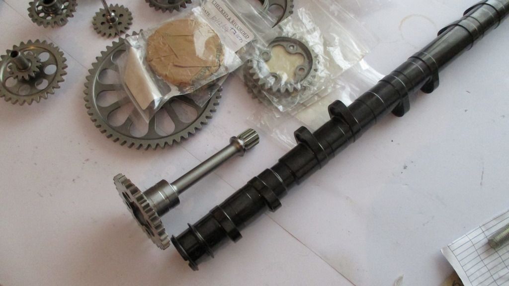
As some of you may know - the camshaft was driven with a quill shaft - this shaft acted as a torsion bar and in turn lessened fluctuations in angular velocity.

The DLC coated intake cam as well as the drive quill can be seen below.

Image

Image

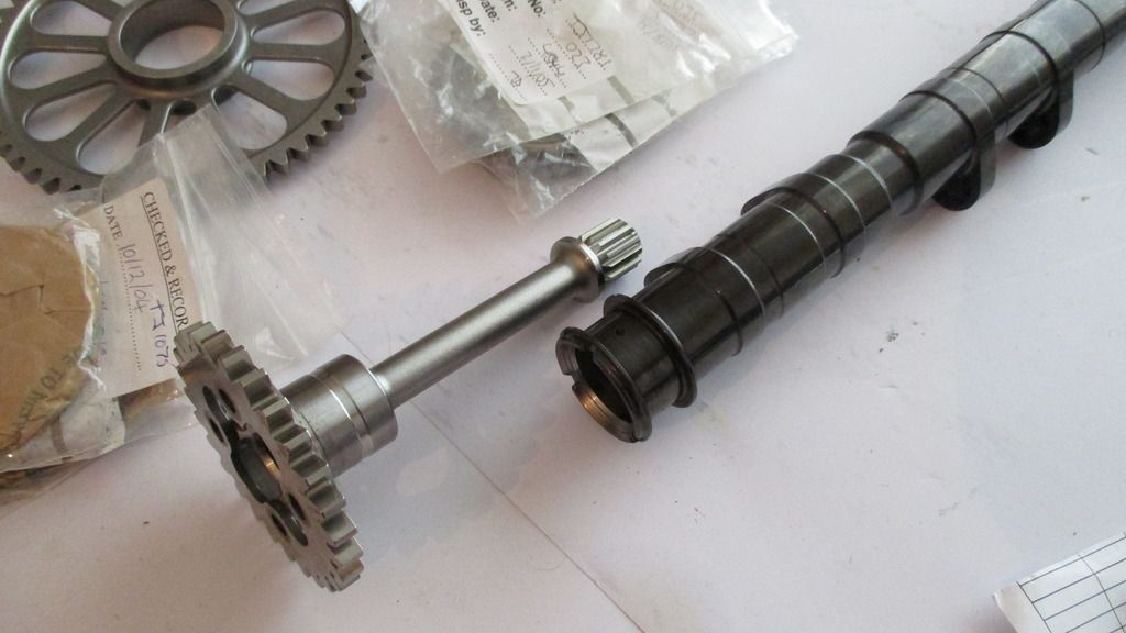
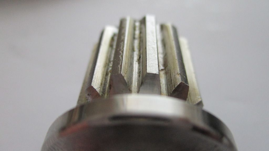
A close up of the quill splines as well as the hollow cam bore below that,

Image

Image

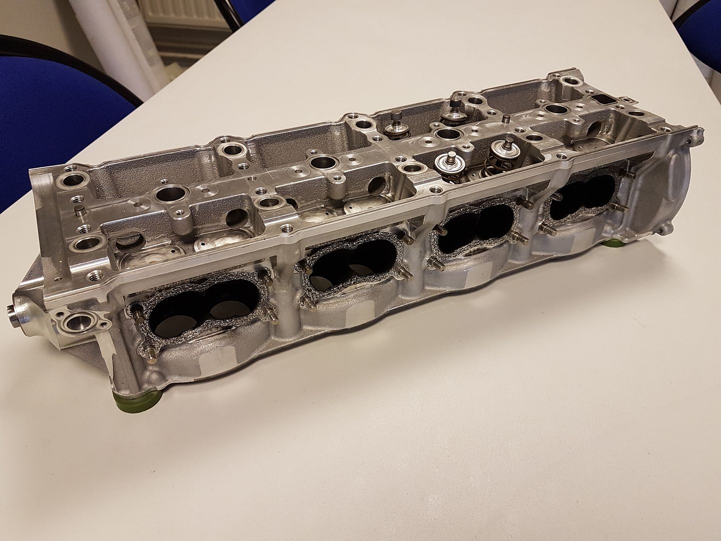
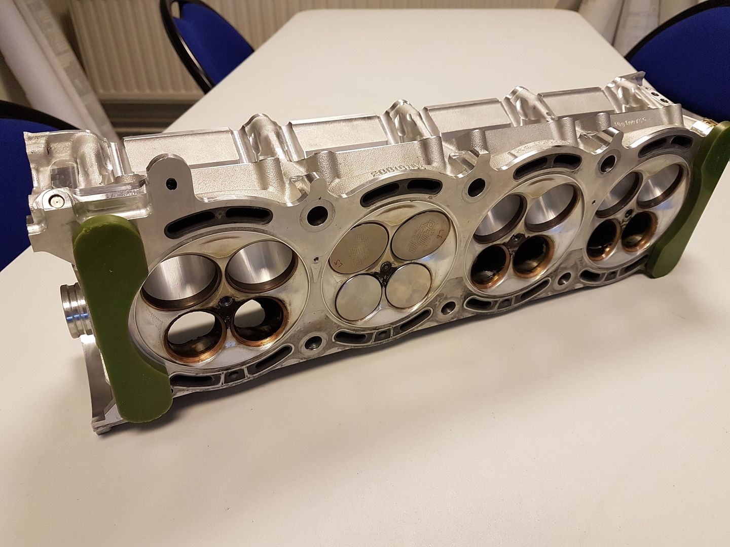
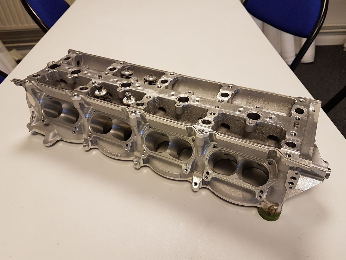
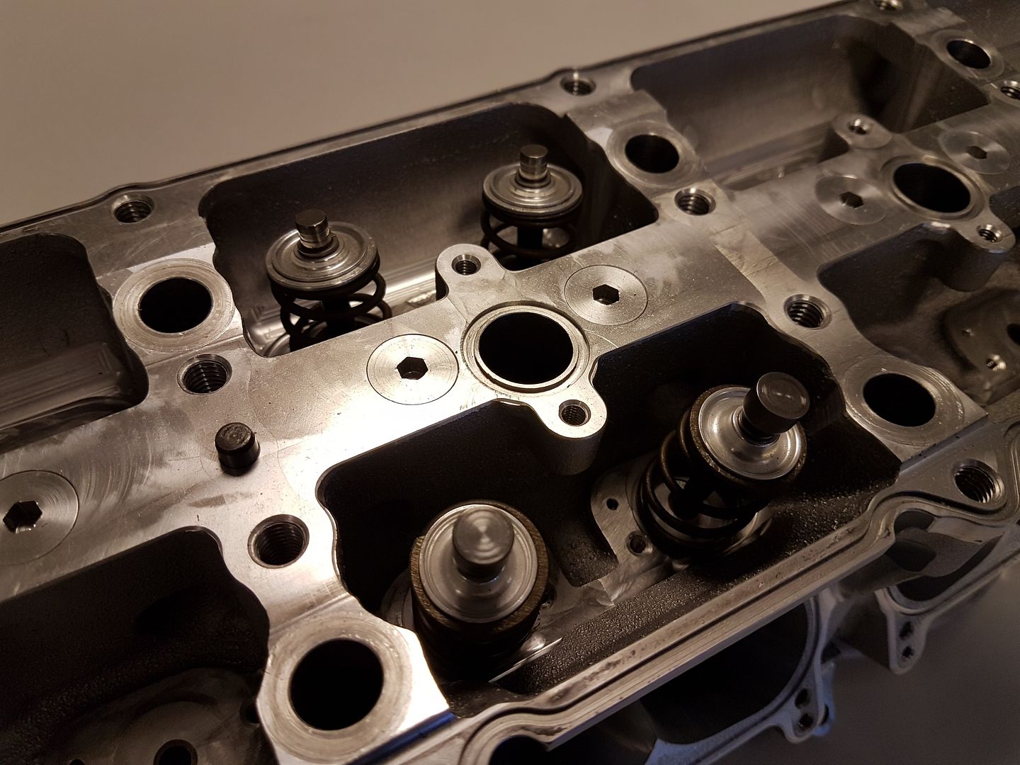
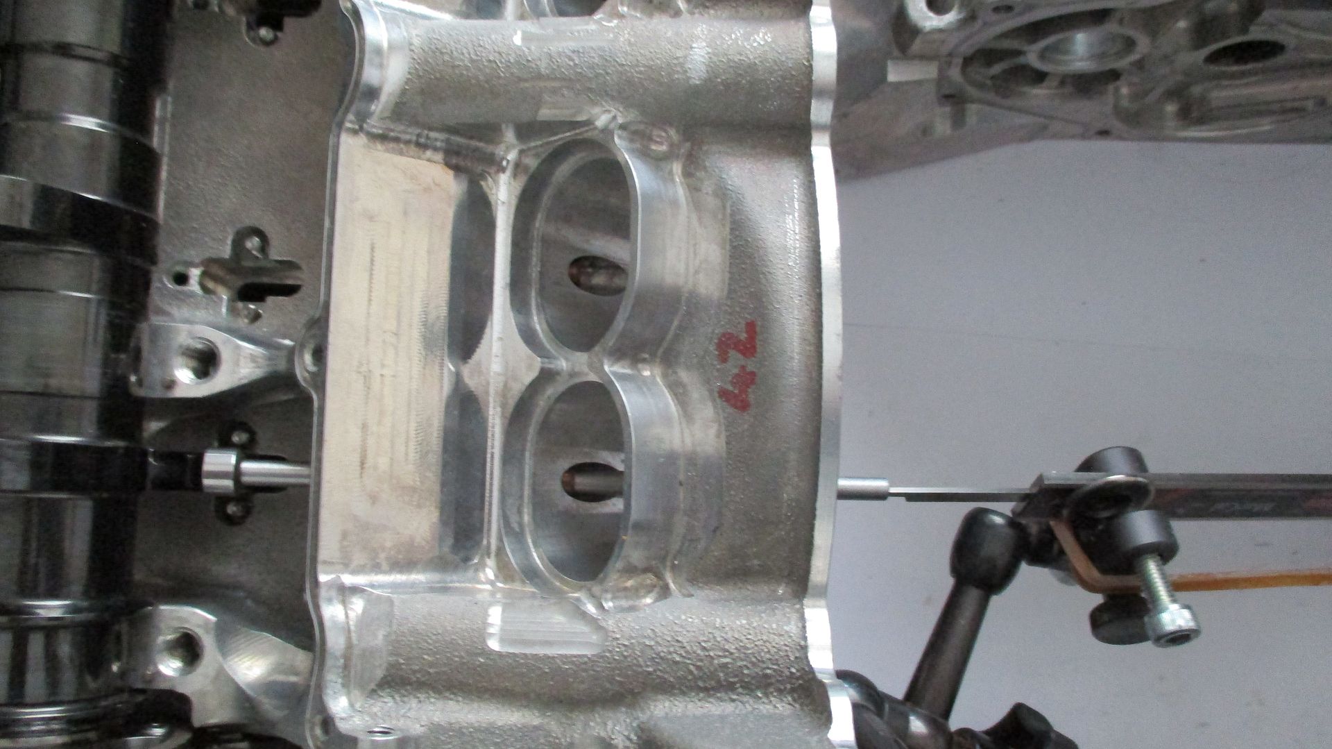
The valve actuation is via finger followers as shown below,

Image

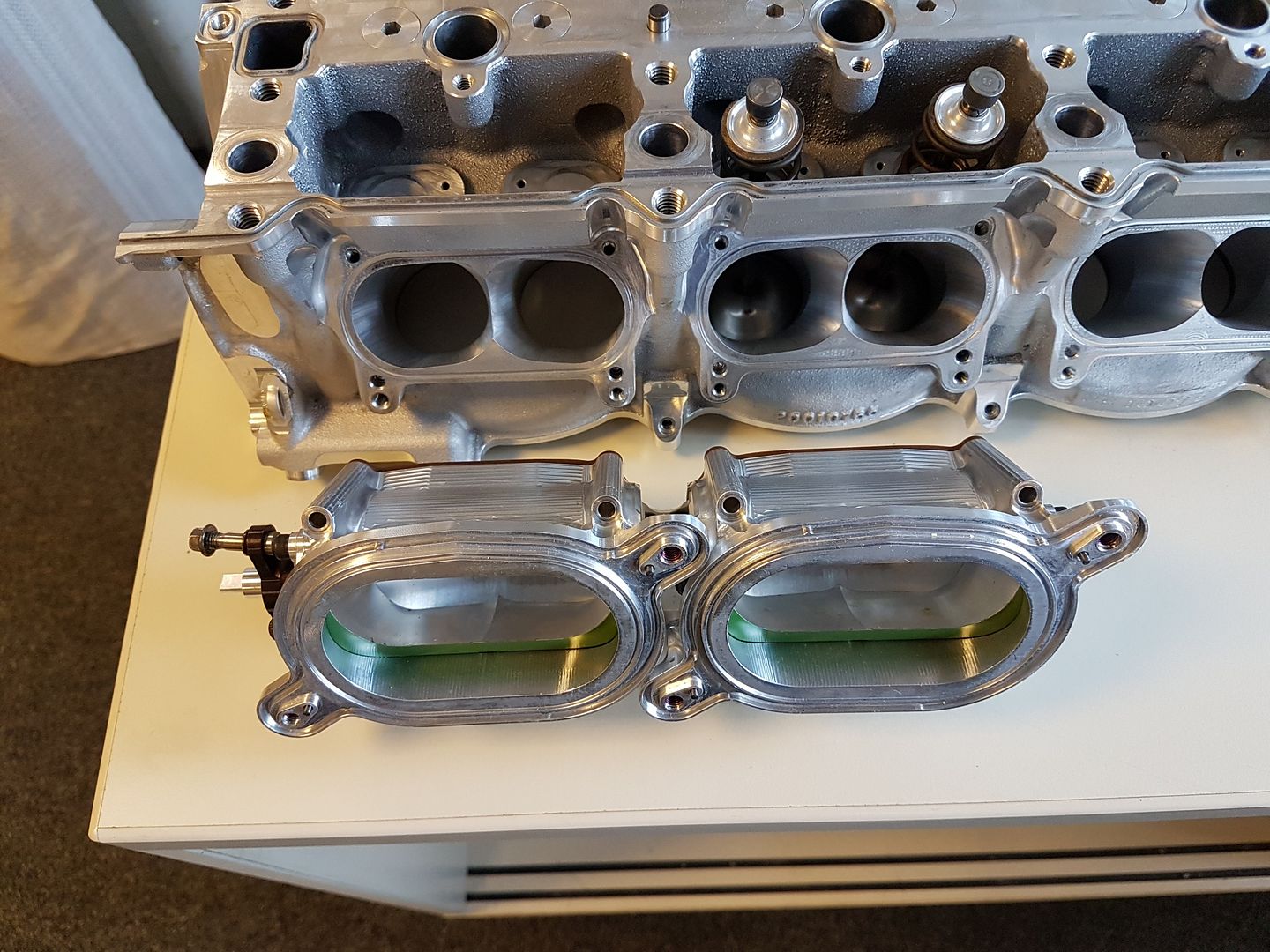
These bolt into pockets along the I-beam head,

Image

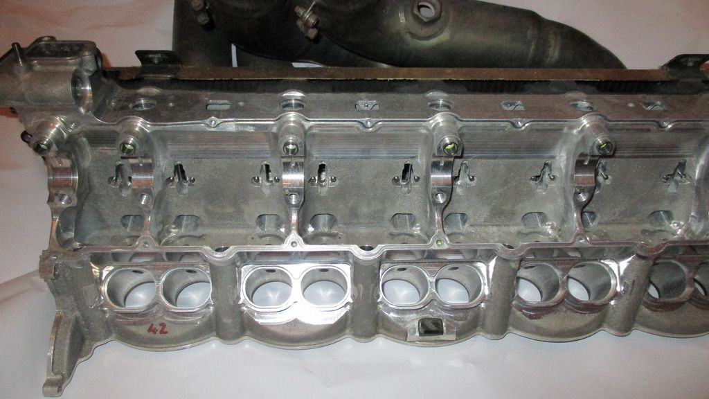
They are cooled with a jet(removed) that is screwed into a drilling above the follower pivot,

Image


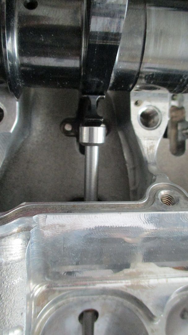
A shot of the cam and finger follower, as well as the mock valve stem used to take the lift measurements,

Image

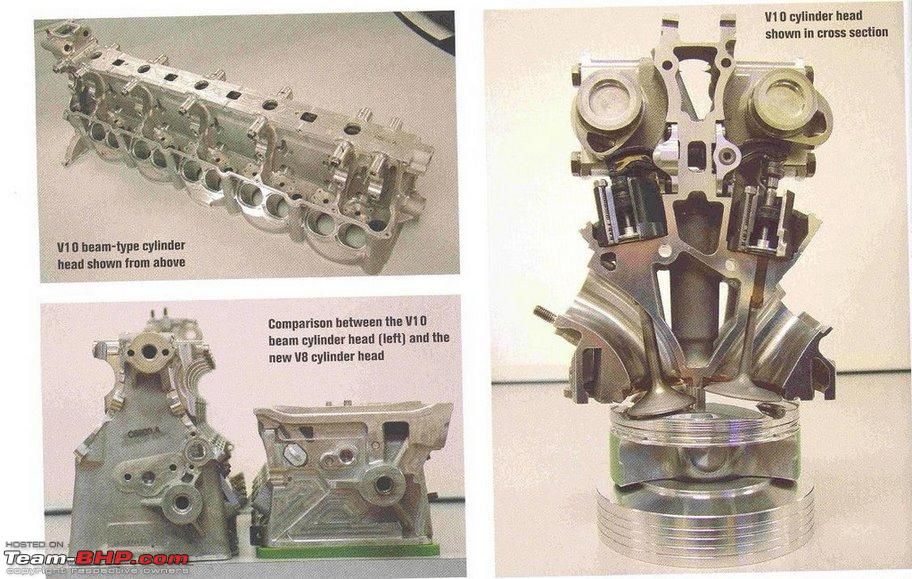
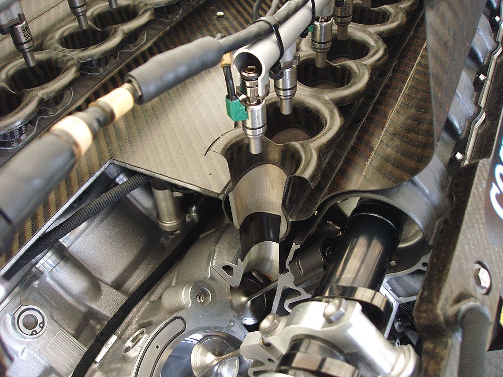
A cutaway of the TJ engine showing general layout,

Image

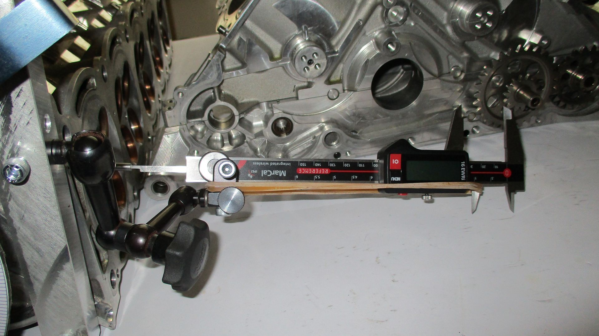
The rig setup shown below used to take lift measurements,

Image

A MAHR wireless calipers was used to create the lift vs angle chart. The calipers has the nice feature of being wireless and can populate an excel sheet on command - which saves a lot of writing and possible errors.

Image

A 360 degree wheel was fixed to the end of the cam. The cam was then rotated to the points where it just started to lift the valve off seat(.01) and also to the point at which the valve came back on seat(0.00). The angular distance between these two points was then halved and this was the position TDC was assumed on the degree wheel. Please note, this may not be the actual TDC point of the engine but it did seem a good place to start taking measurements and in reality a better term would be lobe center line since max lift was seen at 180 degrees.

Image

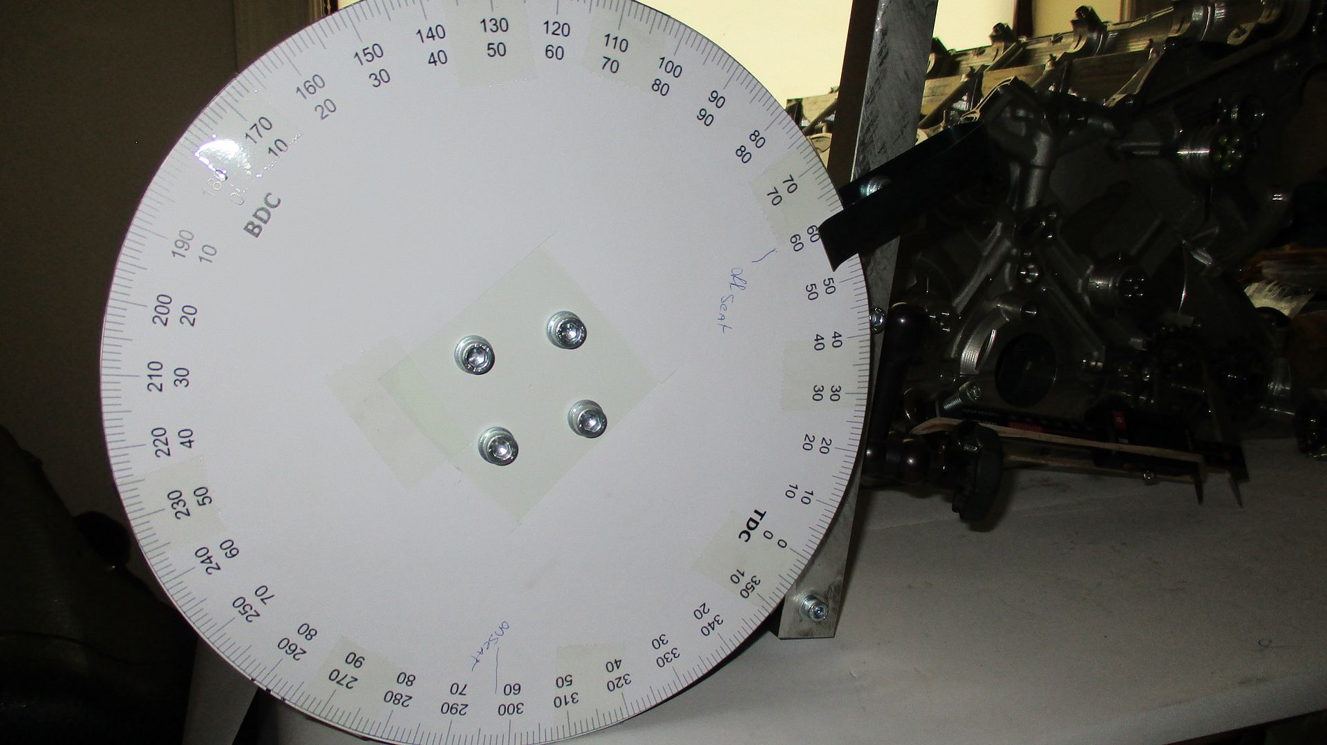
Some key measurements were noted -

Intake valve starts to open at 63 degrees after TDC (''off seat'' on degree wheel - wheel turns clockwise)
Intake valve comes back on seat at 298 degrees after TDC (''on seat'' on degree wheel - wheel turns clockwise)
Max lift - 15.95mm @180 Degrees after TDC.

The plotted graph -

Image

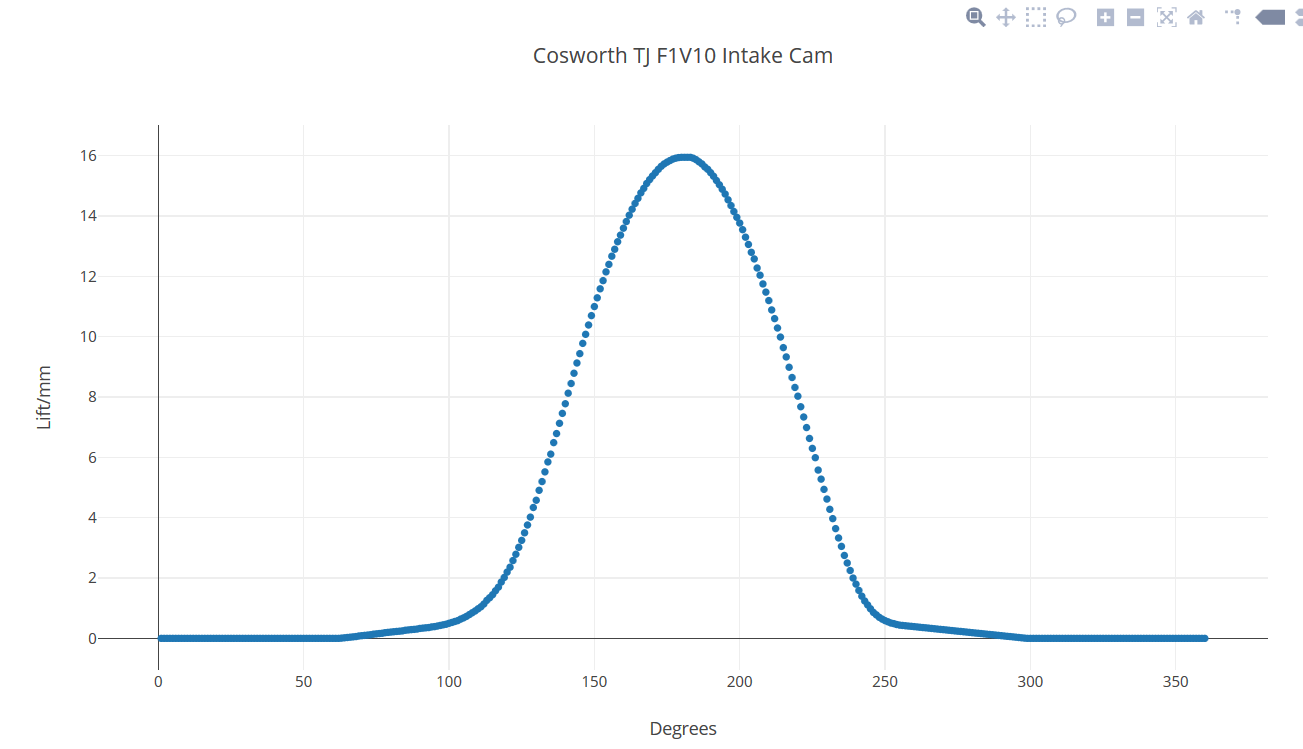
The lift dimensions are listed below for ease of copy and paste should anyone want to analyze the numbers in more detail - Vel, Acc, etc.

Please beware they are to be placed beside a cam angle list from 1-360 degrees.


0
0
0
0
0
0
0
0
0
0
0
0
0
0
0
0
0
0
0
0
0
0
0
0
0
0
0
0
0
0
0
0
0
0
0
0
0
0
0
0
0
0
0
0
0
0
0
0
0
0
0
0
0
0
0
0
0
0
0
0
0
0.01
0.02
0.03
0.04
0.05
0.06
0.08
0.09
0.1
0.11
0.12
0.14
0.15
0.16
0.17
0.19
0.2
0.21
0.22
0.23
0.24
0.25
0.27
0.28
0.29
0.3
0.31
0.33
0.34
0.35
0.36
0.38
0.39
0.41
0.43
0.45
0.47
0.5
0.53
0.56
0.59
0.64
0.68
0.73
0.79
0.85
0.91
0.98
1.05
1.14
1.26
1.35
1.45
1.58
1.7
1.87
2.02
2.2
2.36
2.58
2.79
3.02
3.25
3.5
3.76
4.02
4.34
4.58
4.91
5.2
5.52
5.85
6.11
6.49
6.79
7.13
7.46
7.78
8.13
8.45
8.79
9.13
9.44
9.78
10.08
10.39
10.7
11
11.29
11.59
11.86
12.15
12.4
12.67
12.9
13.15
13.37
13.6
13.82
14.03
14.23
14.42
14.59
14.77
14.92
15.08
15.21
15.33
15.44
15.55
15.65
15.73
15.79
15.84
15.89
15.92
15.94
15.95
15.95
15.95
15.95
15.92
15.87
15.8
15.73
15.63
15.55
15.44
15.32
15.18
15.04
14.89
14.73
14.54
14.35
14.15
13.96
13.77
13.55
13.3
13.06
12.8
12.58
12.28
12.04
11.75
11.48
11.2
10.89
10.6
10.29
9.99
9.64
9.33
8.99
8.65
8.32
8.03
7.68
7.34
6.99
6.63
6.3
5.99
5.58
5.28
4.94
4.62
4.28
3.97
3.64
3.33
3.05
2.75
2.5
2.25
2
1.8
1.59
1.4
1.24
1.11
0.98
0.86
0.78
0.7
0.64
0.59
0.55
0.51
0.49
0.46
0.44
0.43
0.42
0.41
0.4
0.39
0.38
0.37
0.36
0.35
0.34
0.33
0.32
0.31
0.3
0.29
0.28
0.27
0.26
0.25
0.24
0.23
0.22
0.21
0.2
0.19
0.18
0.17
0.16
0.15
0.14
0.13
0.12
0.11
0.1
0.09
0.08
0.07
0.06
0.05
0.04
0.03
0.02
0.01
0
0
0
0
0
0
0
0
0
0
0
0
0
0
0
0
0
0
0
0
0
0
0
0
0
0
0
0
0
0
0
0
0
0
0
0
0
0
0
0
0
0
0
0
0
0
0
0
0
0
0
0
0
0
0
0
0
0
0
0
0
0


Thats all for now - Enjoy,

Brian,
Last edited by Brian.G on 25 Jun 2018, 22:17, edited 1 time in total.
If you think you cant, you wont, If you think you can, you will

daniellammers
1
Joined: 17 Dec 2016, 14:22

Re: F1 V10 Intake Camshaft Spec, a closer look

Post

Those numbers are awesome. But I've got a few questions:

- How did you figure them? Just measure it?
- Do you own the engine?
- What material is the camshaft?
You won't catch me driving a race car that I have built.

- Colin Chapman

Brian.G
334
Joined: 10 Dec 2010, 23:52
Location: Ireland
Contact:

Re: F1 V10 Intake Camshaft Spec, a closer look

Post

daniellammers wrote: โ†‘
25 Jun 2018, 22:01
Those numbers are awesome. But I've got a few questions:

- How did you figure them? Just measure it?
- Do you own the engine?
- What material is the camshaft?
Yes - as pointed out above with a Mahr Digital wireless calipers + degree wheel. 360 measurement points in total.
Yes
Steel'.

Brian,
If you think you cant, you wont, If you think you can, you will

e36jon
66
Joined: 25 Apr 2016, 02:22
Location: California, USA

Re: F1 V10 Intake Camshaft Spec, a closer look

Post

Thanks for the continued generosity with all the details Brian! It's really amazing to see the parts and your analysis just makes it that much better.

Jon

User avatar
PlatinumZealot
551
Joined: 12 Jun 2008, 03:45

Re: F1 V10 Intake Camshaft Spec, a closer look

Post

Always look forward to your threads.
The layout of the head is certainly interesting. I was looking forward to see both cams in place in this weird "wall mounted" layout. Would be great if you could post that.

For the lift profile. It seems the valve opening ramp is gentler than the closing ramp.
Nearly 16mm of lift is pretty aggressive.
The opening angle of 230 degrees is also very aggressive too.
๐Ÿ–๏ธโœŒ๏ธโ˜๏ธ๐Ÿ‘€๐Ÿ‘Œโœ๏ธ๐ŸŽ๐Ÿ†๐Ÿ™

BrunoH
0
Joined: 18 Sep 2016, 13:18

Re: F1 V10 Intake Camshaft Spec, a closer look

Post

great stuff!!

Brian.G
334
Joined: 10 Dec 2010, 23:52
Location: Ireland
Contact:

Re: F1 V10 Intake Camshaft Spec, a closer look

Post

PlatinumZealot wrote: โ†‘
25 Jun 2018, 23:47
Always look forward to your threads.
The layout of the head is certainly interesting. I was looking forward to see both cams in place in this weird "wall mounted" layout. Would be great if you could post that.

For the lift profile. It seems the valve opening ramp is gentler than the closing ramp.
Nearly 16mm of lift is pretty aggressive.
The opening angle of 230 degrees is also very aggressive too.
Here is an image if the v10 head in question - It was called the I-beam design and gave great stiffness in respect to lightness. However for the CA V8 that followed after - carbon fiber cam covers were banned - thus if they had to make the covers in cast aluminium keeping the I-beam design, the lightness would have been lost. I guess the v8 was a pair shorter too which helped in terms of making it torsionally stiff using a more conventional head design.

Image

The later CA V8 3 piece head shown below - cam bearing ladder + cam cover not shown,

Image

Image

Image

Image

Image


Brian,
If you think you cant, you wont, If you think you can, you will

gruntguru
563
Joined: 21 Feb 2009, 07:43

Re: F1 V10 Intake Camshaft Spec, a closer look

Post

Image
Needs some smoothing but you get the idea.
16mm lift is outrageous! Duration at 1mm lift is 268 crankshaft degrees.
je suis charlie

stevesingo
42
Joined: 07 Sep 2014, 00:28

Re: F1 V10 Intake Camshaft Spec, a closer look

Post

I'm surprised at the relatively short duration.

I guess that this is the advantage of the valve train's ability to accelerate the valve so quickly to such a high lift. I guess the duration measures at 5mm lift would be far in excess of anything normal.

User avatar
turbof1
Moderator
Joined: 19 Jul 2012, 21:36
Location: MountDoom CFD Matrix

Re: F1 V10 Intake Camshaft Spec, a closer look

Post

Very nice piece on this =D>
#AeroFrodo

63l8qrrfy6
368
Joined: 17 Feb 2016, 21:36

Re: F1 V10 Intake Camshaft Spec, a closer look

Post

gruntguru wrote: โ†‘
26 Jun 2018, 05:48
https://i.imgur.com/XhG0Gb0.jpg
Needs some smoothing but you get the idea.
16mm lift is outrageous! Duration at 1mm lift is 268 crankshaft degrees.
Interestingly, if you CMM a poorly ground cam and use the measured lift profile to differentiate acceleration you end up with very similar high frequency "errors" which in reality do excite spring frequencies and fatigue them much quicker than a perfect acceleration curve would suggest.

Brian, thanks for another great post. If you're happy to supply dimensions for the entire valve train I'll sign up to mock something up in CAD and see how much we can learn from this - torque to turn, dynamic behaviour , cam stresses etc.

User avatar
strad
117
Joined: 02 Jan 2010, 01:57

Re: F1 V10 Intake Camshaft Spec, a closer look

Post

Thanks Brian =D> ...I'll have convert those numbers to inch measurements to wrap my head around them.
To achieve anything, you must be prepared to dabble on the boundary of disaster.โ€
Sir Stirling Moss

User avatar
Zynerji
110
Joined: 27 Jan 2016, 16:14

Re: F1 V10 Intake Camshaft Spec, a closer look

Post

Would anyone mind explaining the quill shaft, what it does, and why it's useful in this application? It would just seem to add a variance to the position of the valve in my mind, leading to possible in-cylinder collisions with the piston.

Im super interested in understanding this concept, so any explanation from the group would be most welcome!

Tommy Cookers
620
Joined: 17 Feb 2012, 16:55

Re: F1 V10 Intake Camshaft Spec, a closer look

Post

it should reduce that variance (and damage)
by decoupling (reducing the frequency response of) the camshaft to the torsional vibration (oscillation) within the crankshaft rotation
avoiding would otherwise be high amplitude responses (resonance) in the camshaft and cam drive rotations
Last edited by Tommy Cookers on 26 Jun 2018, 23:49, edited 1 time in total.

User avatar
Zynerji
110
Joined: 27 Jan 2016, 16:14

Re: F1 V10 Intake Camshaft Spec, a closer look

Post

Tommy Cookers wrote: โ†‘
26 Jun 2018, 23:26
it should reduce that variance
by reducing the frequency response of (decoupling) the camshaft
avoiding would otherwise be high amplitude responses (resonance) in the camshaft and cam drive rotations
Thank you. Is this used in any production engines?