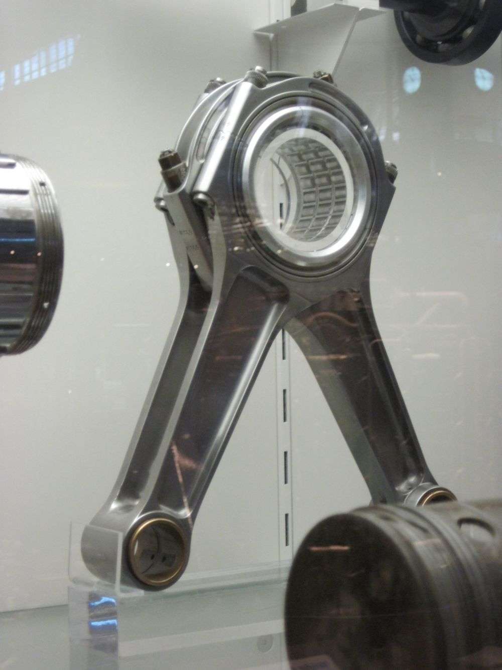
F1 Conrods

All that has to do with the power train, gearbox, clutch, fuels and lubricants, etc. Generally the mechanical side of Formula One.
63l8qrrfy6
368
Joined: 17 Feb 2016, 21:36

Re: F1 Conrods

Post

e36jon wrote:
25 Sep 2018, 01:50
I love a challenge, so off to Google I went in search of Mercedes splayed bolt F1 rods. Yeah, not happening. I did find this though:

Ran across this today as well. It's a MMC rod with a polymer coating aimed at the drag race crowd. It's 'almost to market' for four years now (Hence no link)... Anyway, shows the thinking Mudflap was referring to:

https://imageshack.com/a/img921/7838/oAjdNR.jpg

Doing the web search also pointed out the 'splayed 4-bolt main caps' used in these same engines, but for different reasons...
Hey Jon,

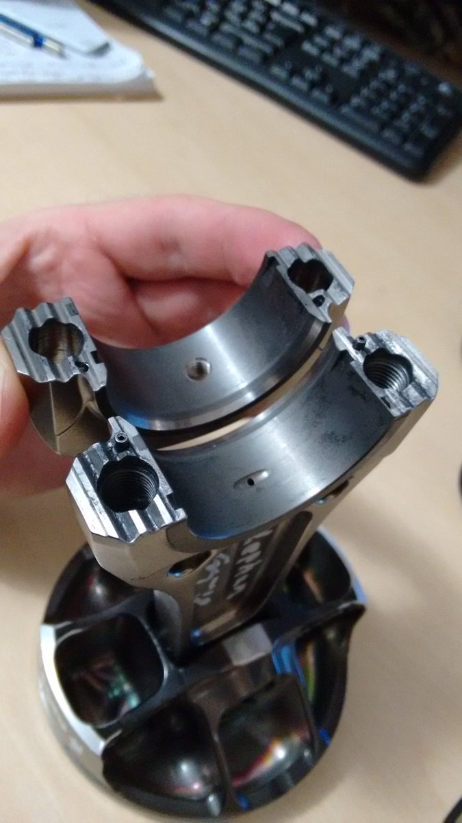
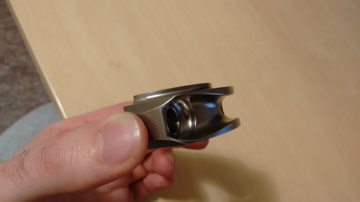
Yes, this is exactly the rod bolt configuration they have used!
I did a bit of searching and found a patent :http://www.freepatentsonline.com/20040107794.pdf

To be fair though the more I think about it the fewer structural reasons I see for having the bolts like this:
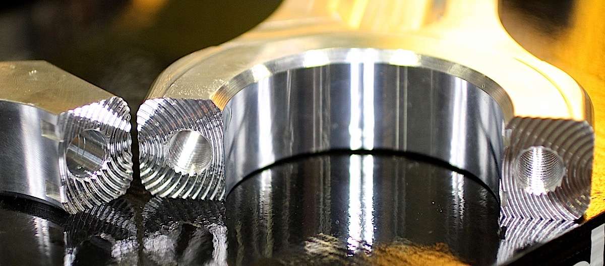
1)Having the bolt head located closer to the parting plane increases the alternating loads on the bolt.
2)Thread not breaking through creates a thin section close to the last thread which is also the thread experiencing the largest alternating stresses! Virtually all of the modern racing rods shown on the first page have break out threads with a huge radius on the last thread (best seen in the Honda rod cross section). Plus you can't easily measure bolt stretch (you can do it ultrasonically but not even F1 teams to that !).

On the pro side the splayed bolts move the bolt cap up which means that the cranktrain can drop lower - this is absolutely critical in F1 (see the rod swept volume explanation in the Honda paper).

I don't really buy the "increased lateral stability" reason given in the patent either - provided that the joint doesn't open or slip the bolt orientation shouldn't really influence bore stiffness. I think it will only change the deformed bore profile. I do need to look into it to actually convince myself though.

As for MMCs used in rods I've only ever heard of SiC in Ti matrix so my guess is that's what they're using.

e36jon
66
Joined: 25 Apr 2016, 02:22
Location: California, USA

Re: F1 Conrods

Post

Greetings Mudflap

The yellowish rod with the angled bolts is an aluminum MMC (Sorry, can't remember the full material spec.). For the drag-race crowd that's not crazy, and he's competing directly with regular aluminum rods. His claims were reduced weight relative to the standard aluminum + greater longevity + improved oil-shedding due to the polymer coating. If you need more info search "Kirk Jager Rods". You might be back in time for X-Mass...

Here's a full description from 2004(!):

The "Ultimate Aluminum Connecting Rod"
So revolutionary it's patented!

Aluminum Ceramic Composite Structure

Higher tensile, torsional, shear and bending strength
Chemically inert, will not corrode
Can be used with ANY type of fuel or lubricant
70 Rc outer surface

Infused Fluoropolymer Matrix - Gives a higher natural lubricity
Allows tighter pin clearance - Will NOT gall
Non-wetting to reduce windage
Provides improved protection against oil failures
Allows tighter rod side clearances

Splayed Rod Bolts - Provides dramatically increased cap stability
Allows shorter, lighter rod bolts - A1 Pro Stock Quality Bolts are standard
Improved Clearance on Camshaft, Block and Oil Pan.

Notable Features:
Deep Cryogenically Tempered
445 gram weight for a 6.00" Small Block Type of Rod
3.480" to 9.120" Lengths Available with Chevy and Honda Big End Sizes
Increments of .005" Available on a Custom Basis

Prices Start at $200 Per Rod for Standard Sizes and Lengths
"UltraLite" Series for 500-1000 HP applications
"HD" Series for 1000-2500 HP applications
"PRO" Series for 2500+ applications

In thinking about the angled-bolt solution, and coming across a hundred articles on angled-bolt mains for pushrod engines, it struck me that main bearing caps seem to be trailing rod caps in terms of locating and stress distribution. I don't want to get too off track, but it would seem like main caps share a lot of the mechanical challenges that rod caps do...

63l8qrrfy6
368
Joined: 17 Feb 2016, 21:36

Re: F1 Conrods

Post

Toyota rods and piston:
The serrated joint with rolled dowels was also used in the CA.

The rainbow on the piston is caused by the PVD process (typically TiN) prior to DLC coating. Mercedes and Cosworth did this too with the latter settling for a simpler xylan coating.


Image

Image


Not F1 but prettier (considering its age):
Image

e36jon
66
Joined: 25 Apr 2016, 02:22
Location: California, USA

Re: F1 Conrods

Post

Thanks for the images MudFlap!

When I would see assembled rods with what appeared to be a serrated interface I always assumed they were like the one shown below, such that they fully constrained the cap location:

Image

In the process of putting this thread together I have seen that's not the case by a long shot. You've mentioned that Pankl have their own play on this with a right-angle arrangement (That I would still like to see.).

And then you have your rods from 1940-something Messerschmitt Bf-109 DB 605 with the same interface. Wow. (More here: https://theairtacticalassaultgroup.com/ ... hp?t=15365)

Image

Other than the Pankl implementation I don't think any of the other patterns are proprietary, so I'd love to better understand what drives the choice one way or the other. Can't say that I love the Toyota solution, but that probably just means I don't understand it...

PS: My best buddy and I were at Laguna Seca for the 'Historics' the year Toyota brought their 2006 F1 car. We happened to be right there when they were getting ready to fire it, in a closed garage. So, we had the treat of a lifetime hearing that V10 come to life and then warmed up. Crazy. Then they went out and set a new outright lap record (Ricardo Zonta driving), breaking Helio Castroneves CART time from 2000 (in a Penske). With no data. With two year old tires. Etc. Woof.

e36jon
66
Joined: 25 Apr 2016, 02:22
Location: California, USA

Re: F1 Conrods

Post

In the process of finding the picture of the Daimler Benz Bf-109 DB 605 rods I also found a picture of the associated piston:

Image

After Mudflap schooled me on the machining on modern F1 pistons being for better cooling of the dome via oil-jets, NOT for weight reduction, I have been wondering why there aren't features to increase the surface area under the dome. Ribs (like above)? Dimples? Bead-blasting? I suspect that weight is too important to have any extra material / weight whose only purpose is cooling.

Anyone familiar with a more modern example (Racing or otherwise.)? I feel like if we would have seen it, it would have been in the prior turbo era, but who knows...

Cheers,

Jon

63l8qrrfy6
368
Joined: 17 Feb 2016, 21:36

Re: F1 Conrods

Post

Hi Jon,

I was specifically talking about that "windowed rib" when I made the comments about piston cooling.
Piston design is an optimization problem where mass has to be reduced while maintaining a minimum strength and stiffness.

Given that an aluminium piston's life halves for every 10 C increase in temperature one can see the role cooling plays in maintaining strength. Fins are not an efficient cooling solution since they add mass and would also interfere with the oil spray. It is much easier to achieve good oil spray coverage with relatively flat bottomed pockets (V8 era pistons) and let the good thermal conductivity of the aluminium do the rest of the job. As mechanical loads increase, the rib height and pin bore thickness also have to increase which gets in he way of the oil and leads to more complex shapes required to allow the spray to reach the crown (ferrari turbo piston).

It is interesting that you mention bead blasting. All modern F1 pistons I know of have had shot peened undercrowns - however this is always done to increase strength rather than to aid heat transfer. There seem to be 2 schools of thought - some manufacturers believe that polishing after peening relieves too much of the compressive stresses (see the texture on the ferrari turbo piston) others believe that polishing leads to higher strenth as it gets rid of stress concentration associated with the poorer surface finish while still maintaining sufficient compressive stress.

e36jon
66
Joined: 25 Apr 2016, 02:22
Location: California, USA

Re: F1 Conrods

Post

Greetings Mudflap

Apologies for my misquote of your earlier answer to my piston 'window' question.

I'll attempt a paraphrase of your reply to my "Why no ribs" question to see if I am getting it:
  • Access to the under-crown is the big-dog in the piston-cooling game, assuming adequate oil-jetting is available.
  • Introducing ribs would not produce a benefit that would justify the increase in mass and likely blocking of oil-jets.
  • Shot-peening (Which is what I meant to say instead of bead-blasting.) is already being widely used but the subsequent texture is viewed as a fatigue / crack-starter risk by some teams.
Once again, thanks for the detailed reply!

Here's some visual support, with 24 oil-jets per piston (!), from Hondas "Development of Reciprocating Parts and Crankshaft in Hondas Third Formula One Era" paper. Note that the oil-jet images are showing the pistons with a section through the 'window' areas that we have been talking about:

Image

There are a lot more images and text around this topic in the paper, so if you are interested it's worth tracking down.

Slightly off-topic: The Rennsport reunion was this weekend and I went down with a friend to see it. Turns out the Porsche-TAG V6 turbo is something you can still buy! They have a kit to put one in your 911. I failed to get a photo, but they are using modern copies of the original parts, including a forged Pankl conrod that is the same form factor as the original...

Cheers,

Jon

63l8qrrfy6
368
Joined: 17 Feb 2016, 21:36

Re: F1 Conrods

Post

Good find,the right hand side picture shows exactly what I was trying to explain.

e36jon
66
Joined: 25 Apr 2016, 02:22
Location: California, USA

Re: F1 Conrods

Post

Stumbled across an older piece from Kevin Cameron on F1 / MotoGP rod bearing tech: https://www.cycleworld.com/2015/10/23/a ... n-insights Also, I am a big fan of his work and can wholeheartedly recommend all of his books.

The really short version being that they eliminated the separate bearing on the big end altogether by coating the rod surface directly! I had not ever heard that before and I certainly haven't seen (or noticed) said treatment on any of the rods in this thread. His post was from 2015, so relevant for the V8's at least:

In this recent F1 process, a very thin layer of copper-lead is deposited into F1 connecting rods by PVD, or physical vapor deposition. This is a “sputtering” process that moves atoms from a target onto a destination surface by ion bombardment. As you might suspect, this is not an inexpensive affair. Because the resulting layer of bearing material is very thin, it is unusually resistant to fatigue and can carry unit loads up to 17,000 psi, a substantial improvement over usual insert-bearing load capacity.

Anyone out there ever seen one of these pieces? Would love any first-hand experience you care to share...

Jon

63l8qrrfy6
368
Joined: 17 Feb 2016, 21:36

Re: F1 Conrods

Post

It's a lot of bull I'm afraid.

F1 engines have used and continue to use copper bearings with a lead-indium overlay. In some cases the bearings are used without a steel backing for better thermal conductivity and to reduce fretting against titanium rods but never has the bearing been replaced by some wonder PVD coating.

Sputter bearings are mostly aluminium based and are very hard compared to traditional copper electroplated bearings, however they lack the conformability and compatibility required for racing applications. It is true that they are stronger, but lead-indium does work fine at quite a bit over the 17000 psi unit pressure stated in the article.

e36jon
66
Joined: 25 Apr 2016, 02:22
Location: California, USA

Re: F1 Conrods

Post

Thanks Mudflap!

I had a hunch it would be you weighing in on this. It was a beautiful dream while it lasted: Better durability, better thermal conductivity, lighter weight due to no bearing + reduced rod dimensions, and unicorns...

Cheers,

Jon

e36jon
66
Joined: 25 Apr 2016, 02:22
Location: California, USA

Re: F1 Conrods

Post

Greetings all

A new treat from Ebay, a 'mid-nineties McLaren-Mercedes' rod and piston:

Image

Image

Image

Image


There is a lot of weird happening here, so I don't know what to believe. A three ring piston? That doesn't seem like the norm. The mis-matched (seemingly) rod-cap? Maybe what was handy from the junk pile? The spacers under the rod bolts? The rough and sharp piston crown? And so on.

As ever, your collective feedback appreciated.

Jon

gruntguru
563
Joined: 21 Feb 2009, 07:43

Re: F1 Conrods

Post

The ratio of inlet/exhaust valve head diameter looks a bit too extreme for F1. I would expect 90 - 95%.
je suis charlie

User avatar
coaster
16
Joined: 30 Jun 2012, 05:10

Re: F1 Conrods

Post

Can we get a like button for those pictures?
I used to set up lycoming conrods for my boss during my apprenticeship, some were forgings with the skin partially milled of and polished all over. Phallic goodness!!!

e36jon
66
Joined: 25 Apr 2016, 02:22
Location: California, USA

Re: F1 Conrods

Post

Greetings Coaster

A pleasure to meet another fanatic. You should treat yourself to ownership, as having one of these F1 rods on the desk is a constant source of amazement. The Cosworth TJ ones in particular seem to be widely available for ~$50 U.S....

Regarding the photos, with only a few exceptions they are all stolen property. I use Google Image for my searches and just grab what I need. So, your 'like' would just be to let others know that you like something...

Cheers,

Jon

Post Reply