A little mid-thread reminder that the content of this thread is essentially a shortened version of the content of the book “Classic Racing Engines” by Karl Ludvigsen:
http://www.bentleypublishers.com/automo ... tents.html
https://www.amazon.co.uk/Classic-Racing ... +Ludvigsen
Further explanation in the first post of the thread:
viewtopic.php?p=805009#p805009
******************************************************************
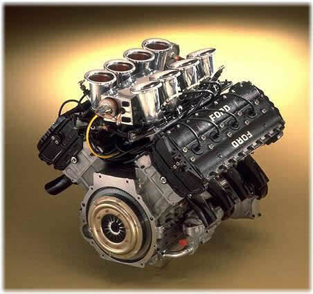
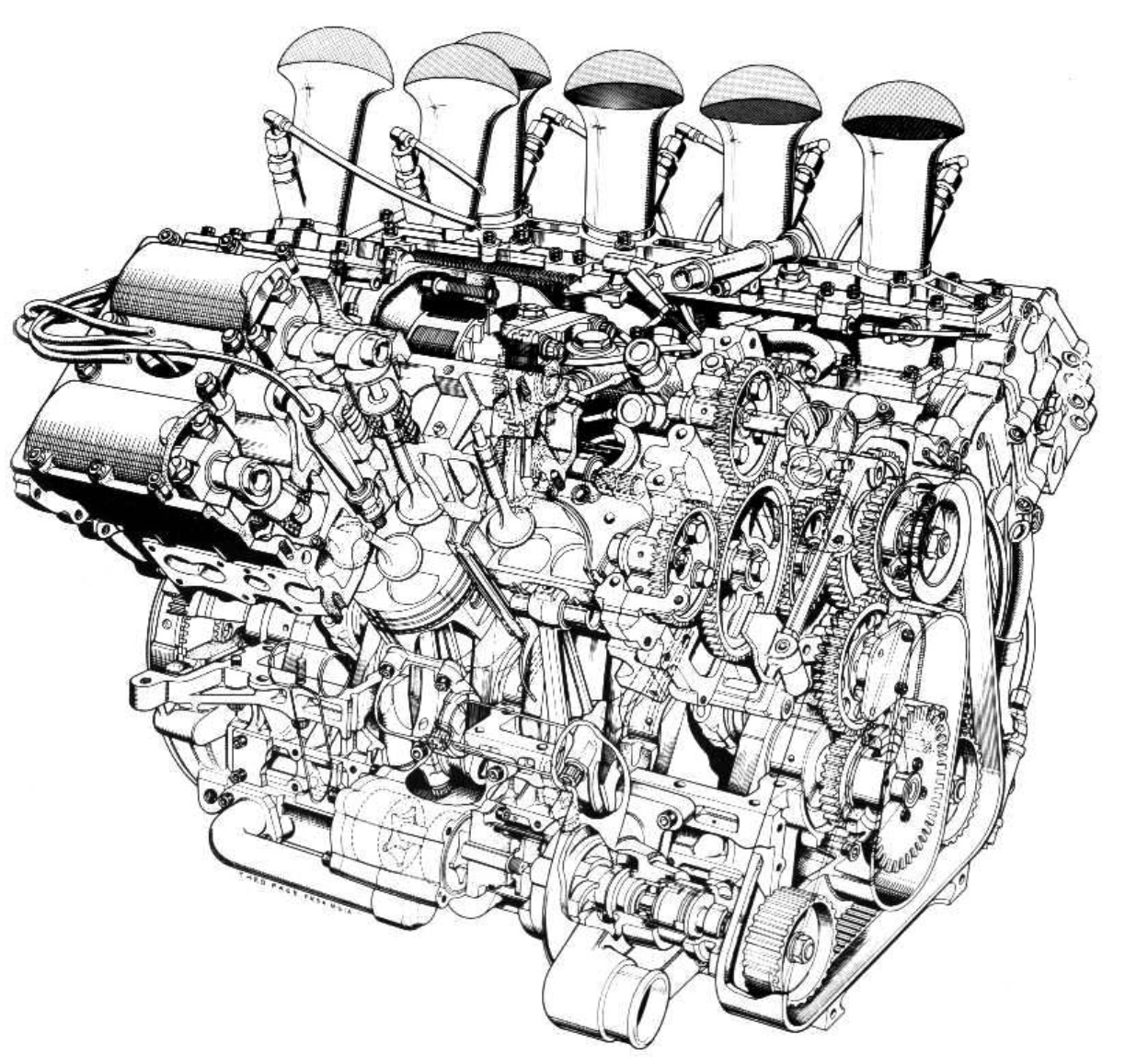
1967 Ford DFV 3-litre V8
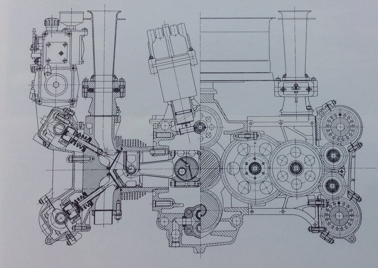
1967 Ford DFV 3-litre V8: Keith Duckworth’s DFV was a major contributor to the revival of the four-valve cylinder head as an optimum means of producing racing-engine power. The first Cosworth engine to have four valves was its formula 2 four based on the Ford Cortina block, which had a 40 degree included angle between the stems. For the GP engine this was reduced to 32 degrees with an 11:1 compression ratio, this narrow angle allowed the top of the piston to be flat except for four machined recesses to accommodate the valve heads near top-dead-centre, a configuration that produced an advantageously compact combustion chamber with at its centre, a single 10mm spark-plug.
Valve diameters were 34.5mm for the inlets and 29mm for the exhausts, both were closed by paired coil springs, lift was 10.4mm and timing was initially: Inlet opens 58 degrees BTDC, inlet closes 82 degrees ABDC, exhaust opens 98 degrees BBDC, exhaust closes 58 degrees ATDC.
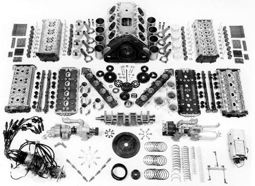
The aluminum-alloy cylinder head was so designed that one casting served for both cylinder banks. It was held down by 10-main studs and additionally by 4-short studs along both sides of the head at its periphery extending downwards from the head. The seal with each cylinder was effected by a copper ring, set in a groove machined at the join between the flange at the top of the cylinder liner and the surface of the block.
The cylinder centre distance was 104.8mm and the offset between cylinder banks was 20.3mm. atop the head was a one-piece aluminum-alloy casting which served as a carrier for both cams and tappets. This was held down by long studs from the tops of the heads which also served to retain the cam bearing caps and, down the 2-centre rows, the shallow magnesium cam covers.
The steel cams were carried in 5-plain bearings, the wider centre bearing having a groove to supply oil to a hole through which it entered the hollow camshaft to distribute oil to the other bearings. Inverted-cup tappets were made of steel and contained shims for clearance adjustment. An inlet port that was as straight as possible to the valve was created. The inlet ports were oval at the head face and bifurcated internally to the 2-valves.
Above the ports were slide throttles, whose slides were supported on balls and rollers for free movement. Between the throttles and the ports were short stub ‘manifolds’ that contained passages through which the excess fuel returned by the injection pump could flow, and be cooled, on its way back to the fuel tank. They were refrigerated to around 30 degrees centigrade by the internal vaporization of the fuel. Fuel was injected just above the slides by a Lucas system. Operating at 110psi, its distributor delivered the fuel starting at 30 degrees after TDC.
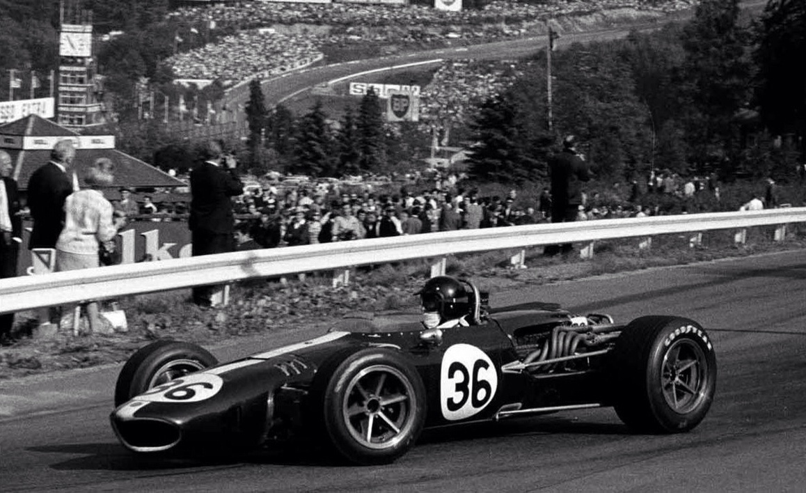
This system was suspect when in their first 4 or 5 races, the V8 in the Lotuses were beset by erratic misfiring. Suspecting the fuel filters in the metering units for the Canadian GP in August 1967 Chapman added some large filters which bypassed the smaller built-in ones. This stopped the misfiring.
Lucas electronic ignition and electronic rev-limiting were used. With peak power being reached at 9000rpm Cosworth started out in 1967 with the limiter at 9500rpm, then moved it up to 9800rpm before the end of the season. Before the end of the season the fuel-injection metering unit, the ignition distributor and a small alternator were combined in a single unit mounted in the vee of the engine, and driven by a small –diameter shaft from a gearbox driven by the timing gear train at the front of the engine. 2-compouded (back-to-back) gears were included in the train at the front that drove the camshafts.
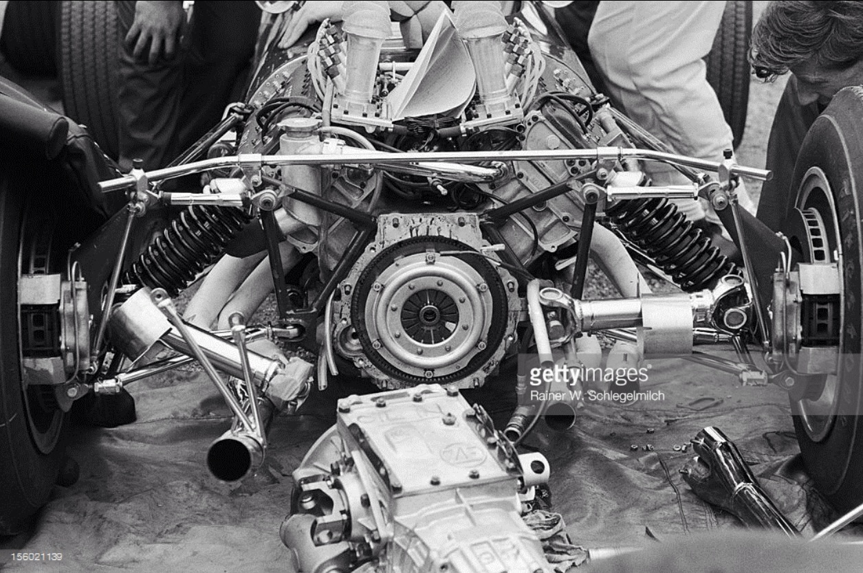
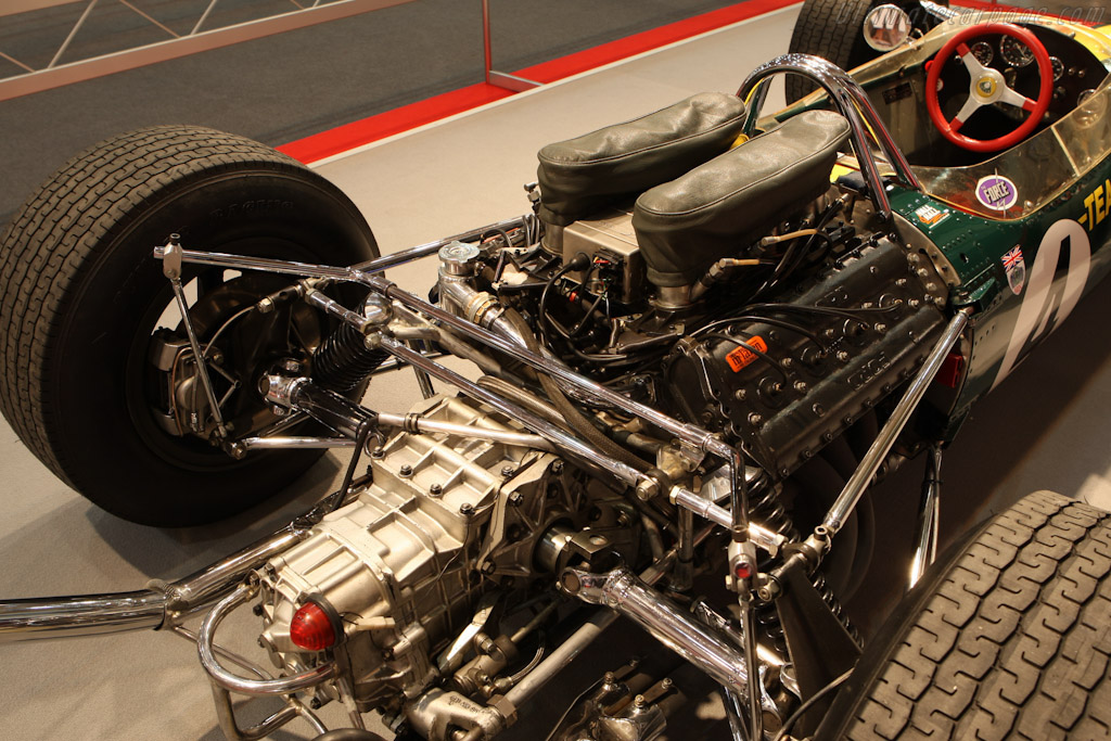
In the DFV early years this experienced various failures that led to intensive development of every aspect of the cams and gears, including making the later of vacuum-remelted steel. The final solution, introduced in 1971, was to introduce into the hub of the second compound gear 12 miniature torsion bars which were able to absorb the energy spikes that were troubling the gears. A shaft through the engine’s magnesium front cover turned a sprocket which powered a cogged rubber belt to drive the engine’s remaining accessories. This solution was adopted because Chapman and Duckworth had agreed that the engine would serve as the rear chassis element of the new Lotus 49 and that should not be encumbered with pumps on its front face. So side mounted pumps were introduced.
Sprockets drove a row of pumps along each side of the crankcase, first on each side was a coolant pump both being interconnected, on the right side also included an oil scavenge pump and a rotary oil/air separator. On the left side a mechanical fuel pump and an oil pressure pump as well as an oil filter were carried.
The aluminum-alloy cylinder block was cut off at crankshaft centerline, wet cast-iron cylinder liners clamped in the block at their top flange and grooved at the bottom to take 2-orings were used. Only 2 of the 5 main bearings, the second and fourth, had conventional caps (from 1971 the other three caps were integral with the aluminum casting of the engine’s bottom cover) in the original engine all 5 caps were carried by the cover. Carried in Vandervell thin-wall bearings was the crankshaft, forged from EN40 steel. This was of flat design counterbalanced accordingly.
Originally an oil pressure of more then 85psi was needed to ensure that oil reached the main and rod bearings, but in 1997 a breakthrough was made to a different network and angling of the internal drillings that performed better than the previous system at only 60psi.
Forged con-rods, 132.8mm long with fully skirted pistons with gudgeon pins retained by circlips with a triple ring pack including a Dykes-type ring at the top and a conventional compression ring and oil ring were used. The rods were polished and then shot-peened. From its first runs the 162kg Cosworth DFV had power, 408bhp@9000rpm to begin with, plus or minus 3 percent depending on the individual engine.
Specifications:
Cylinders V8.
Bore 85.7mm.
Stroke 64.8mm.
Stroke/bore ratio 0.76:1.
Capacity 2993cc.
Compression ratio 11.0:1.
Con-rod length 123.8mm.
Rod/crank radius ratio 4.1:1.
Main bearing journal 60.3mm.
Rod journal 49.2mm.
Inlet valve 34.5mm.
Exhaust valve 29mm.
Inlet pressure 1.0Atm.
Engine weight 162kg.
Peak power 408bhp@9000rpm.
Piston speed corrected 22m/s.
Engine bhp/litre 136.3bhp/litre.
Engine weight/bhp 0.40kg/bhp.