In this thread I will be unlocking a few secrets hidden within this part - The F1 Hydraulic Pump, mainly its construction, operation, and some other features.
The part below is from a Honda F1 Engine but this particular pump was used on many engines and across many Manufacturers - it was used on the Cosworth V10 and V8 for example. It is also worth noting that this model of pump is also used on many aircraft - the A320, 747, 777 and the F-16 Fighter to name just a few.
The F1 Hydraulic Pump is normally driven off the rear of the alternator via a splined input shaft. It supplies pressurized oil around the car to many parts that require motion assist - power steering, throttle control, gearbox control, and so on. Hydraulic actuation has many benefits over cable or electronic control in F1 environments for many reasons - lightness, response time, and durability being a few.
The pump below is a variable displacement axial piston design. It is capable of varying the volume of fluid delivered to maintain system pressure. The major benefit of this pump is that is extremely compact and self contained in terms of varying the pumped volume of oil. An oil feed is simply taken from the outlet pressure port and this oil feed is then used to displace a small piston inside the pump which in turn alters the angle of the swash plate carrier which the piston plungers ride in. These pumps are considered the best in terms of hydraulic pump design for such applications however they are hugely expensive even refurbished due to the extremely high manufacturing tolerances within.
Before we move onto the actual pump, here are some figures relating to the pump in question.
Operating Pressure - 207bar (3000psi)
Maximum RPM - 11,000
Displacement - 0 - 2.46cubic centimeters per Rev (0.15inch)
Max Flow Per Minute - 25.7L (6.8USG)
Dry Weight without customer specific mount flange - 1.18KG (2.6lbs)
Length without customer specific mount flange - 90mm - 57mmW - 80mmH
Materials - Customer specific mount flange - Titanium.
Main gold body - 7 Series Aluminium.
Swash plate piston control housing - Cast Aluminum.
Rear Outlet cap - Cast Stainless.
Internals - Steel/Forged steel.
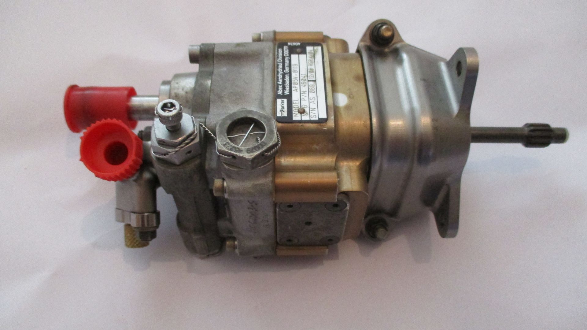
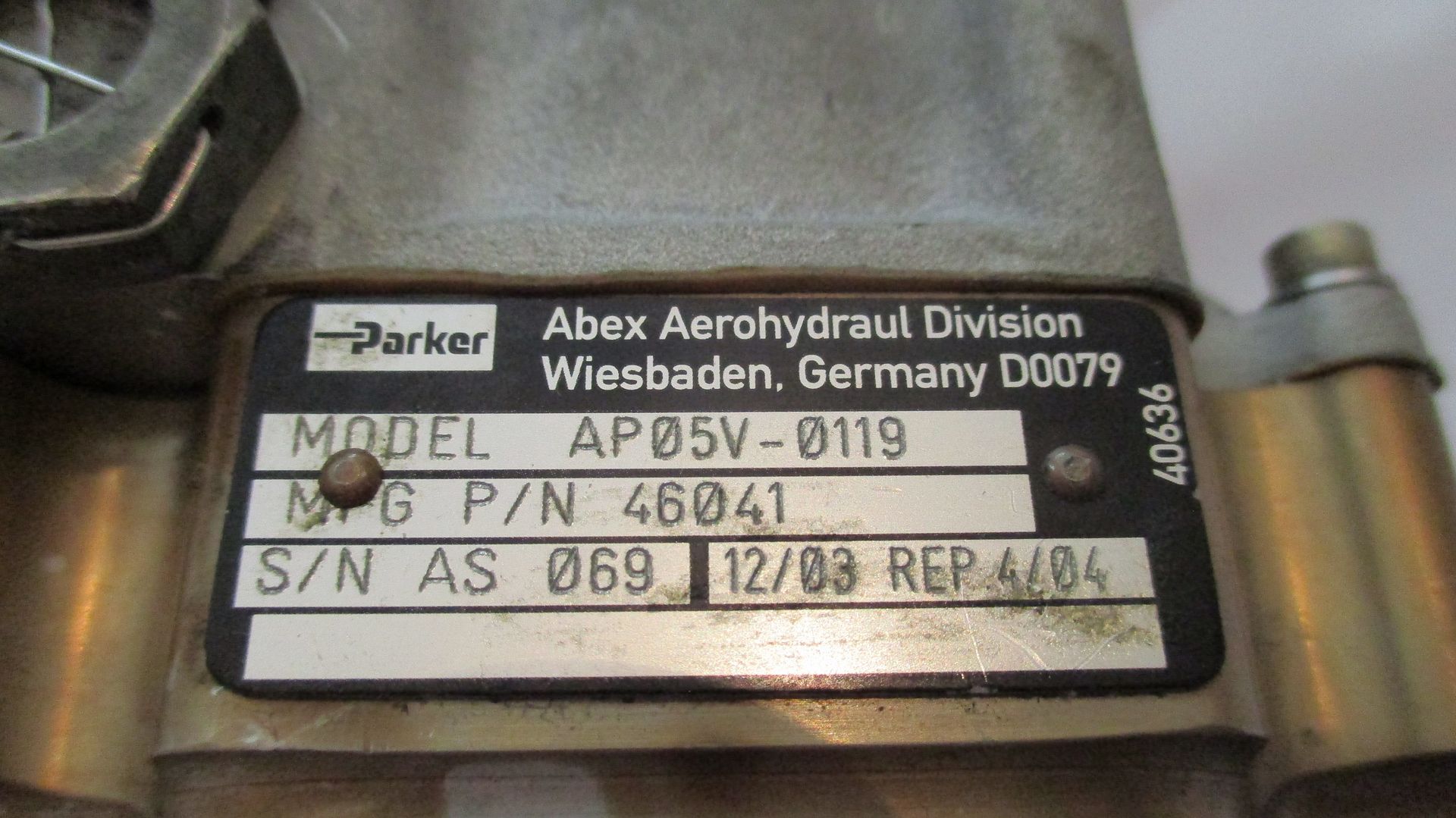
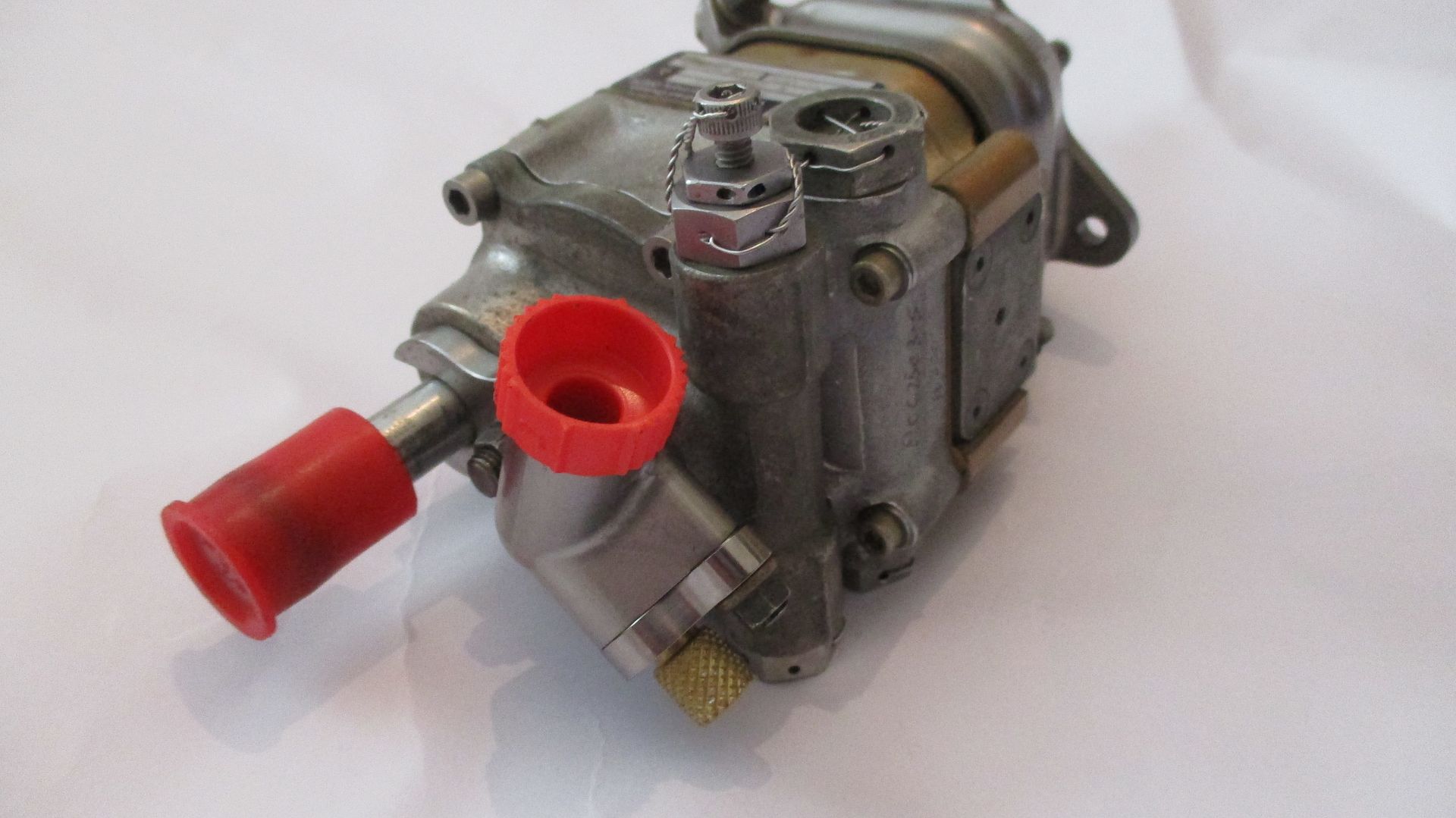
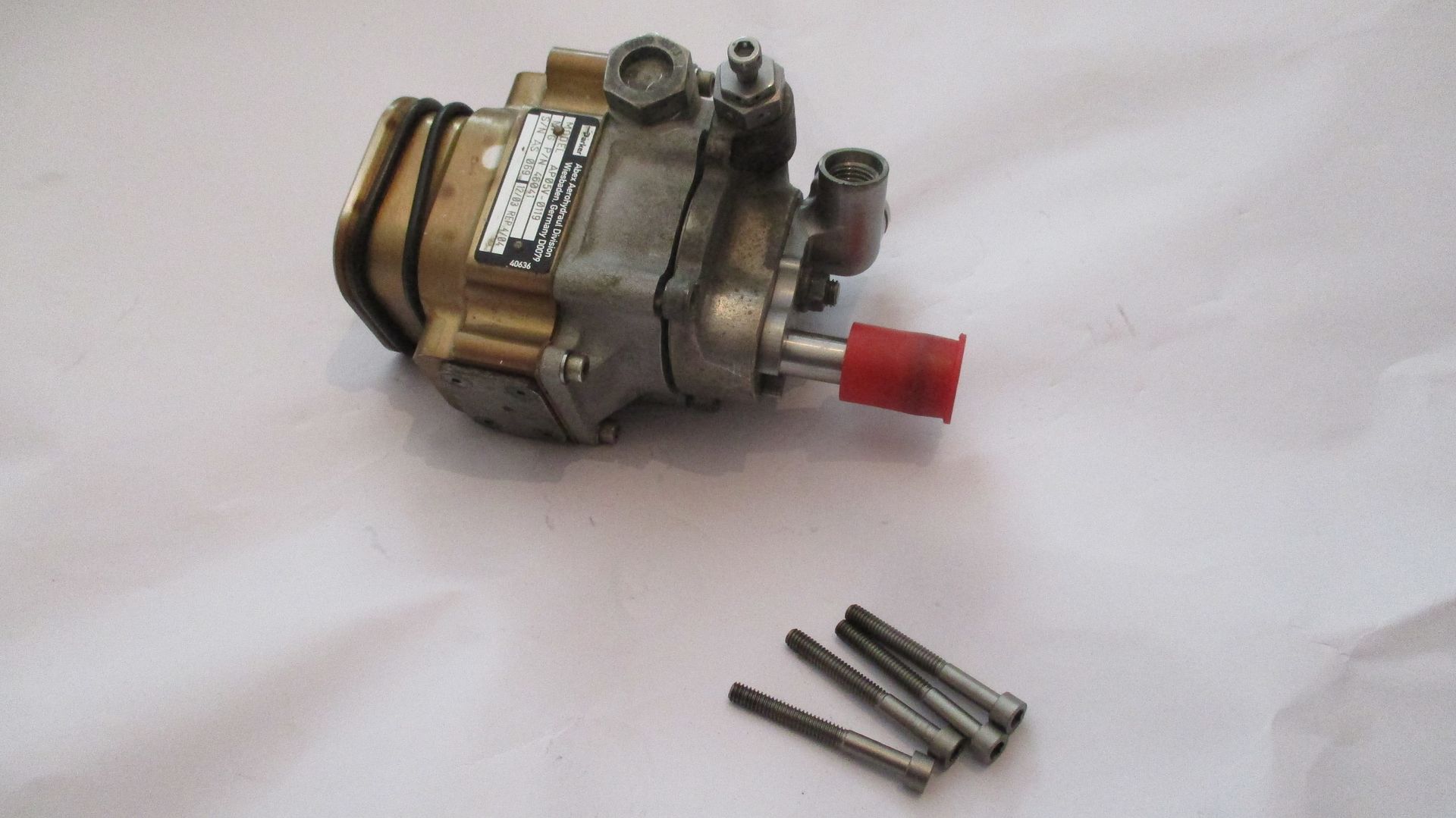
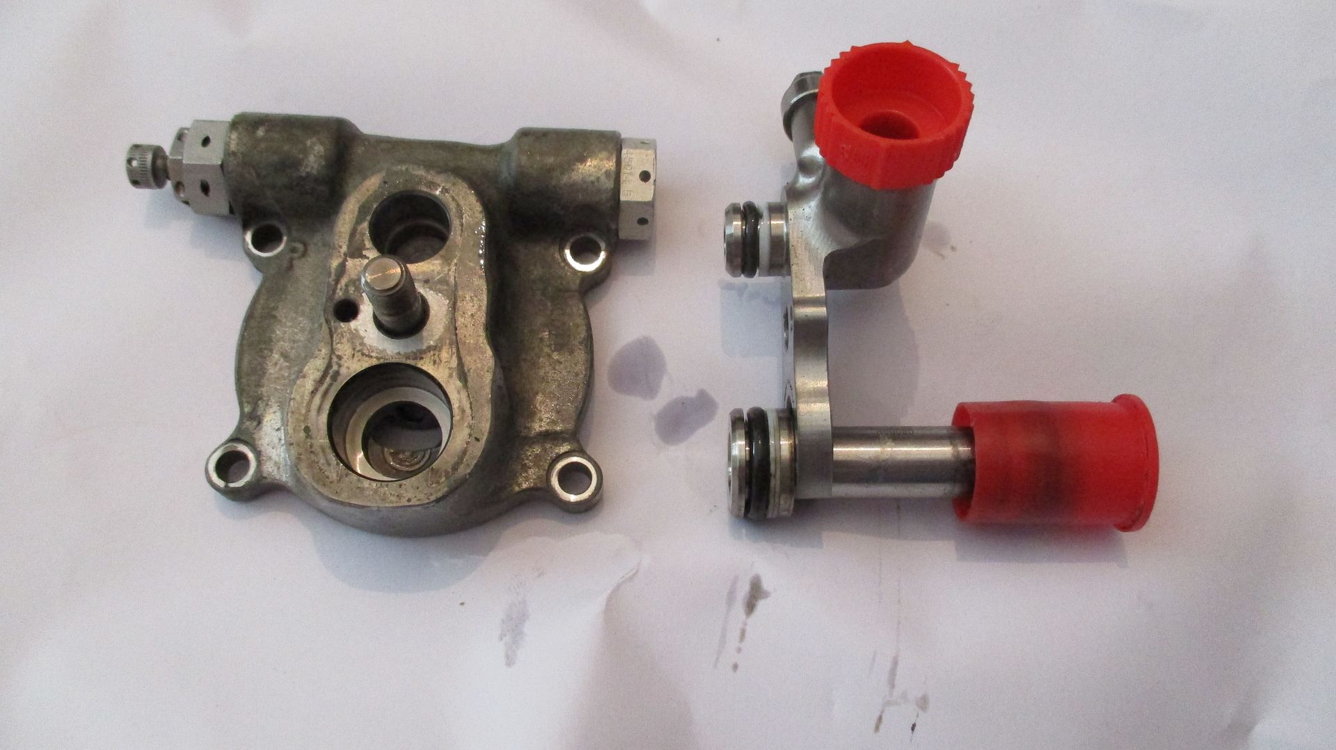
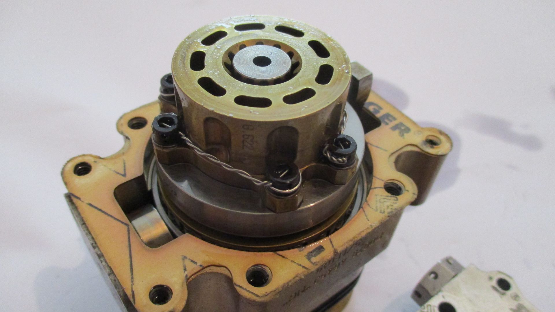
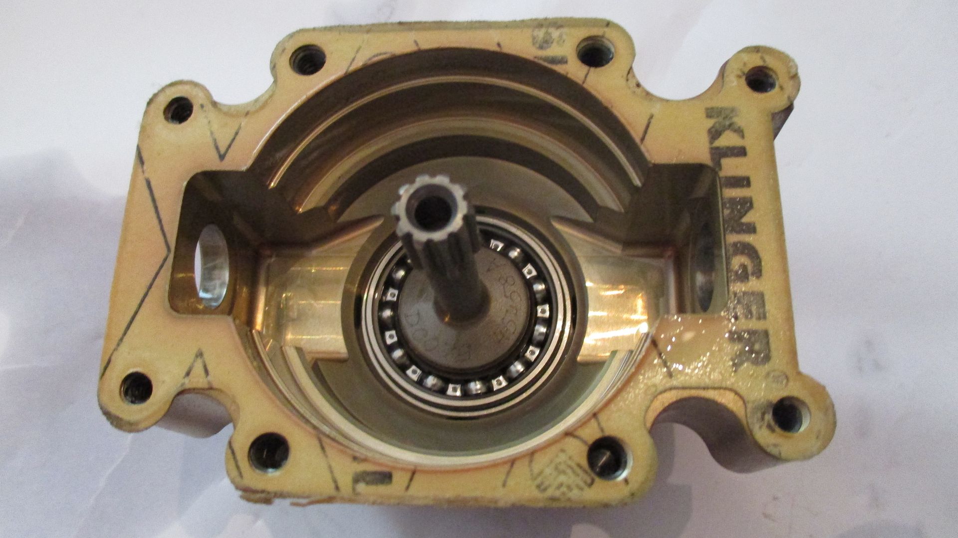
The pump,
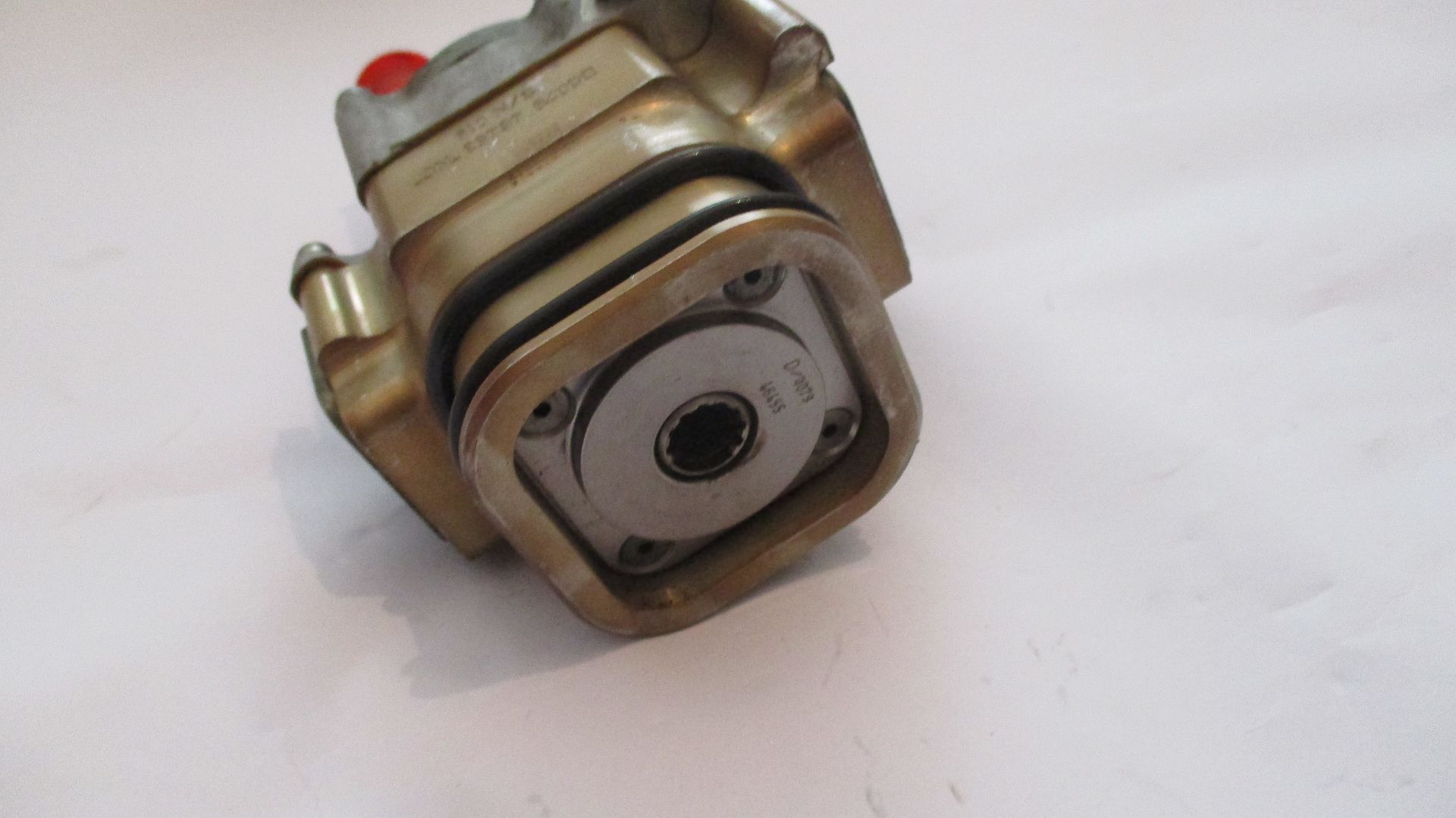
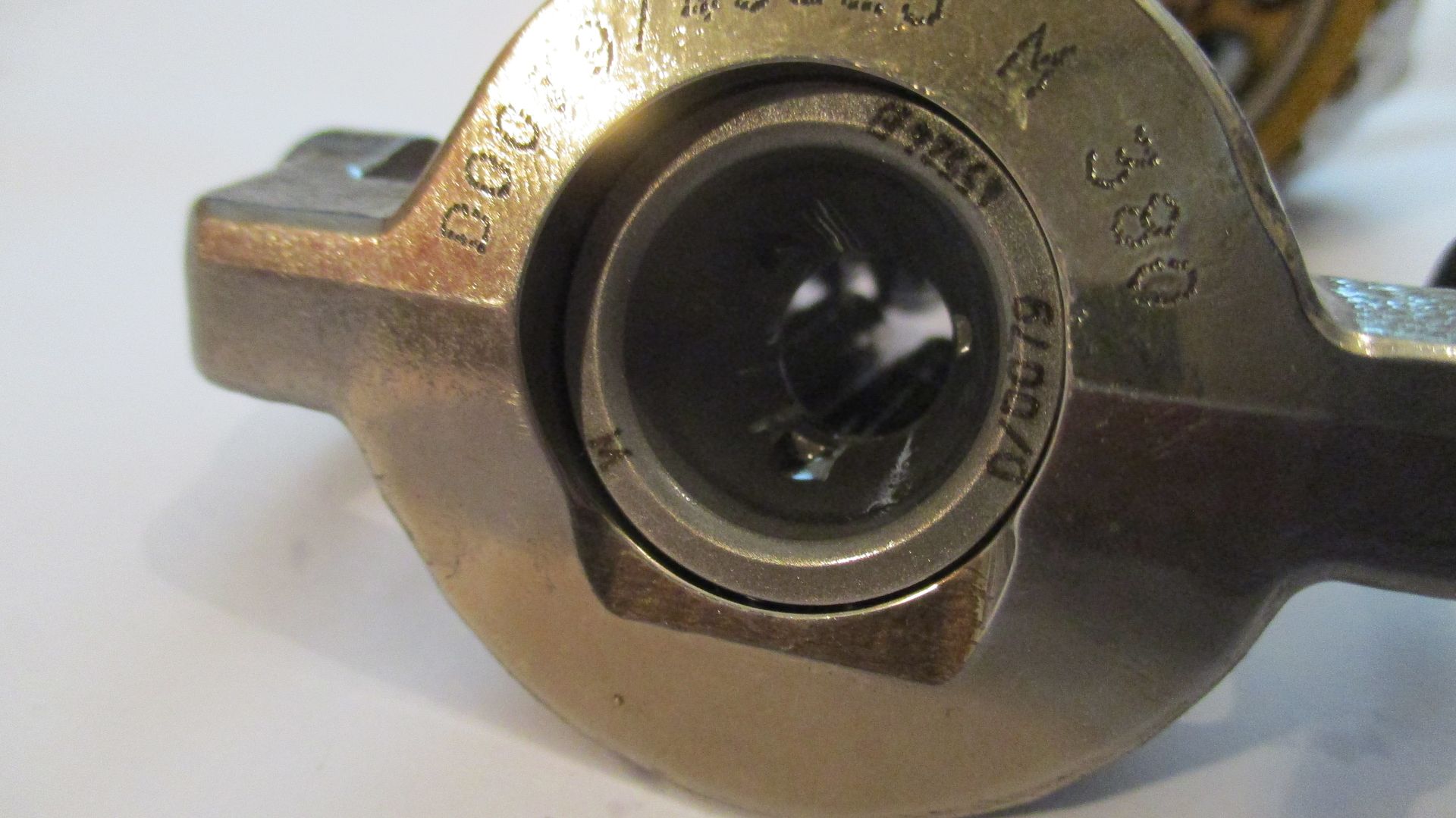
Drive shaft details and mount flange,
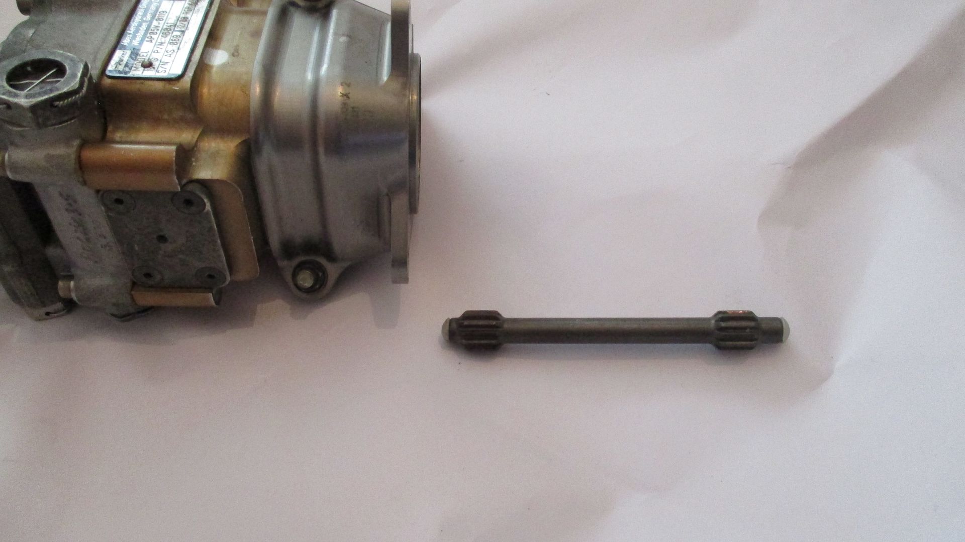
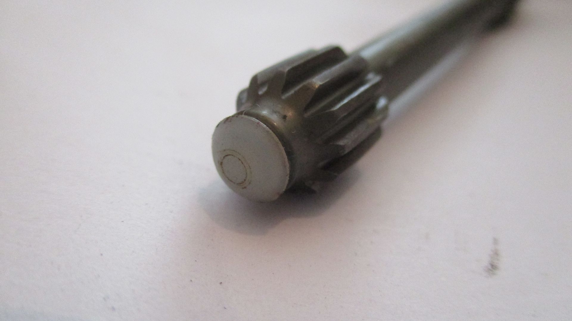
Drive shaft features end buffers to prevent axial fretting on braking and acceleration,
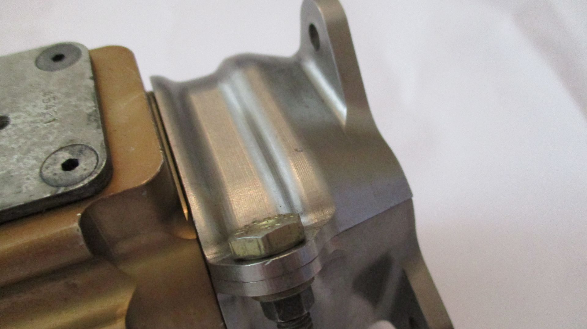
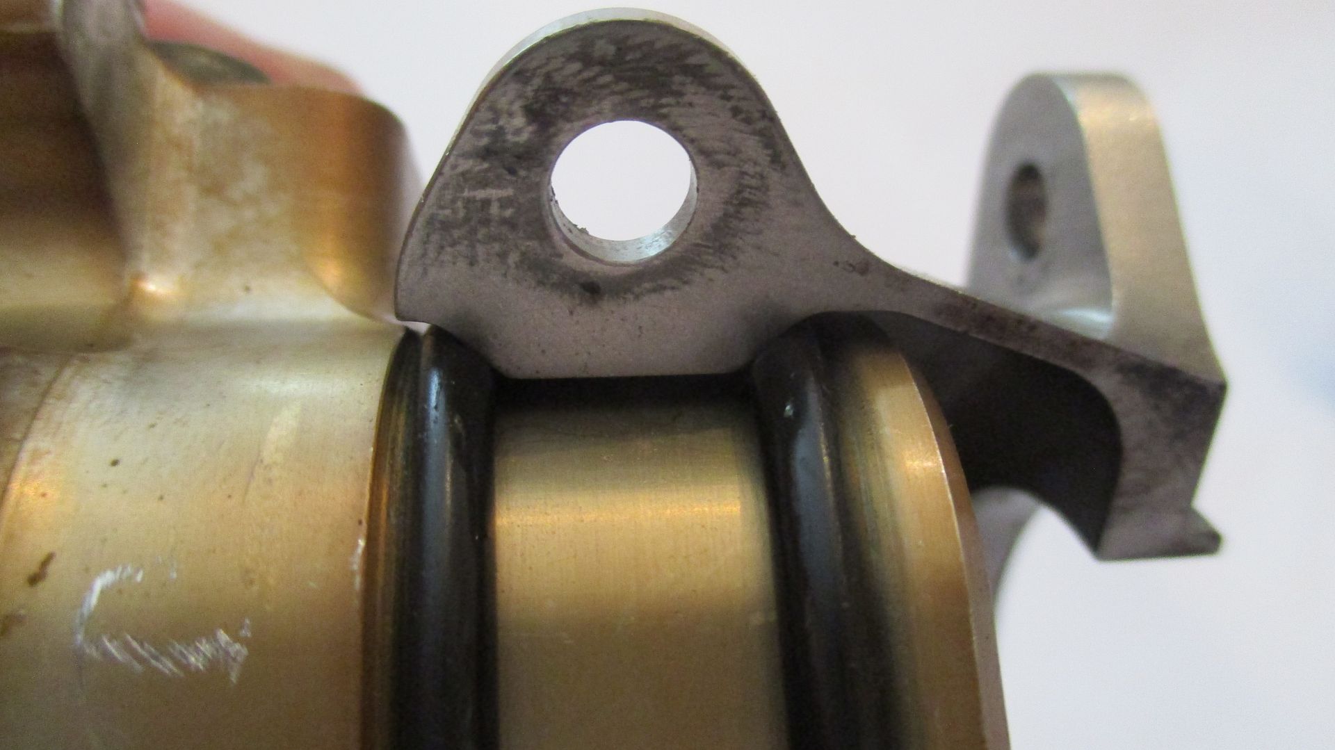
Swash plate pivot pin covers,
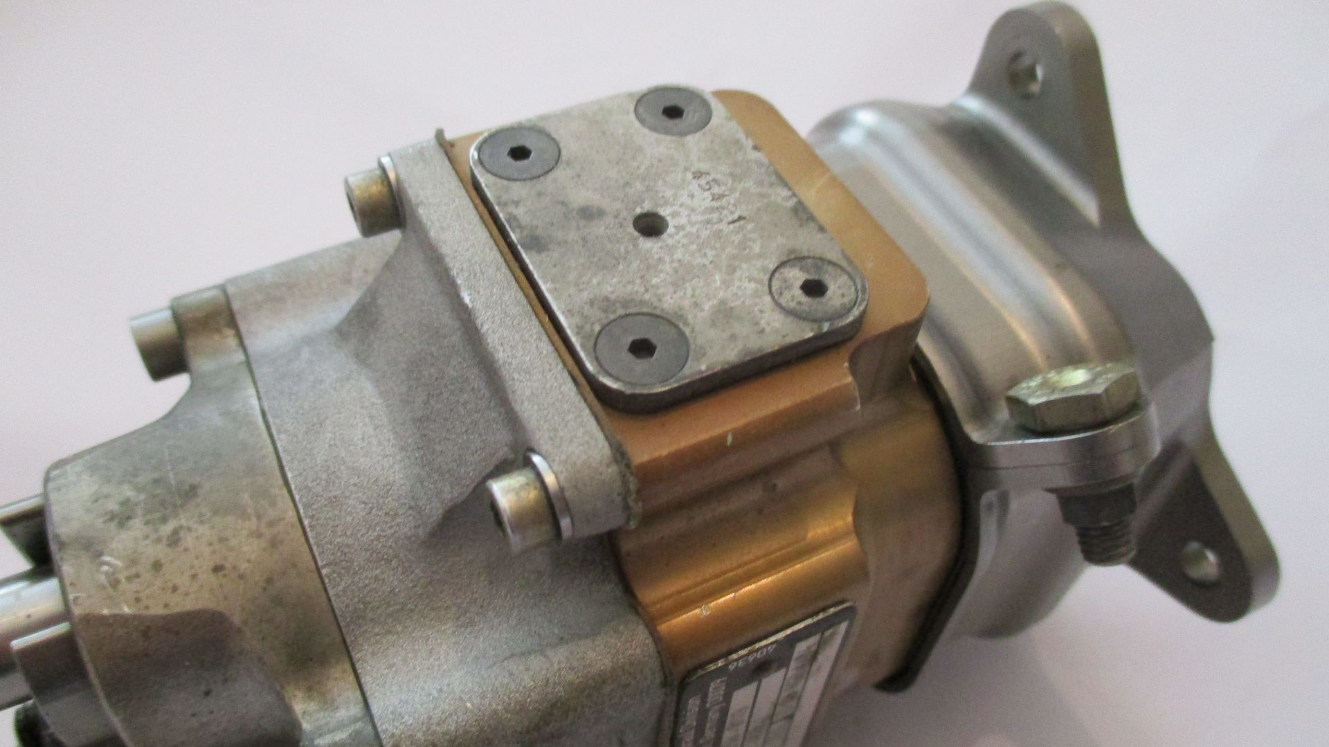
Titanium mounting flange,
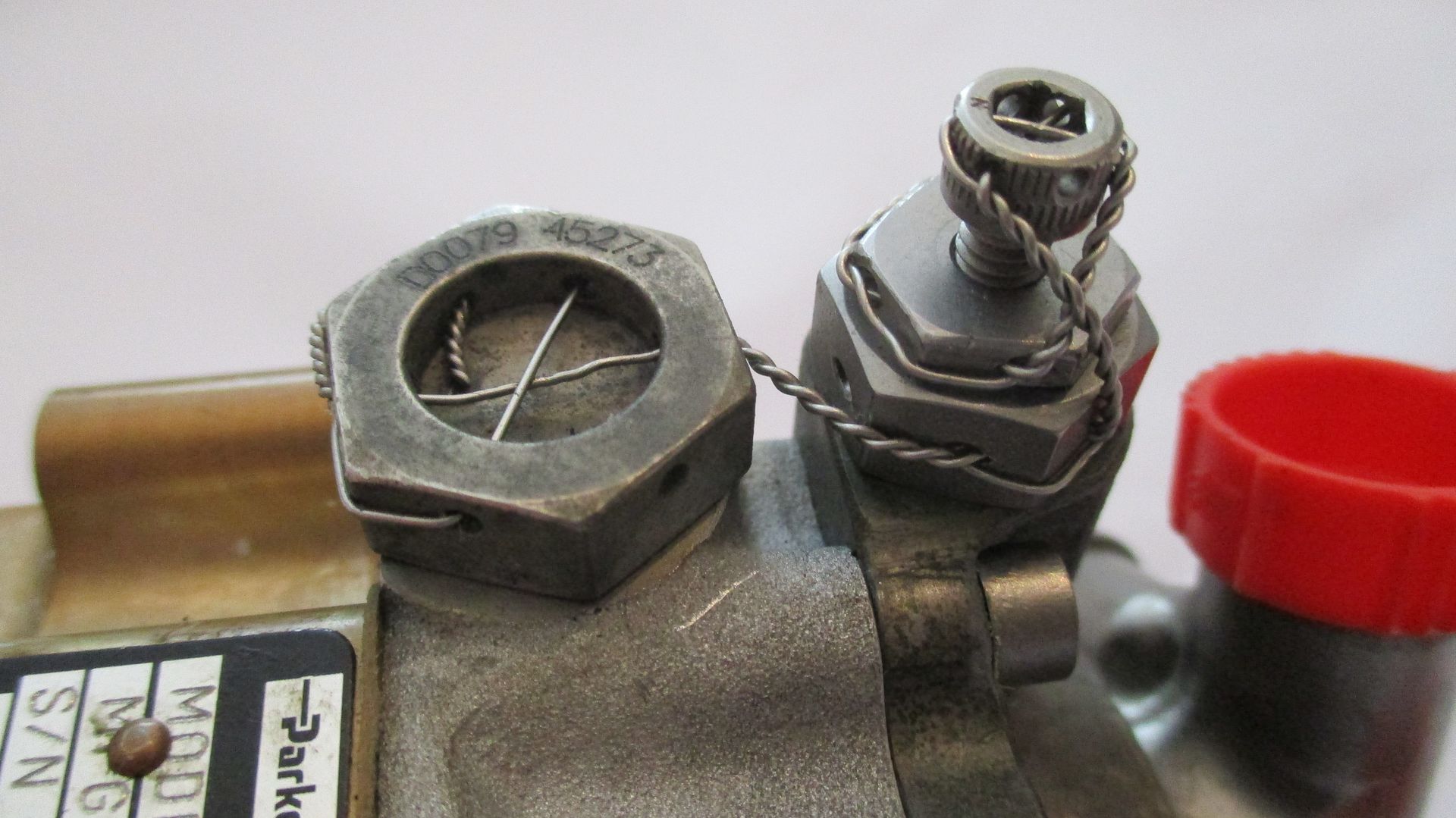
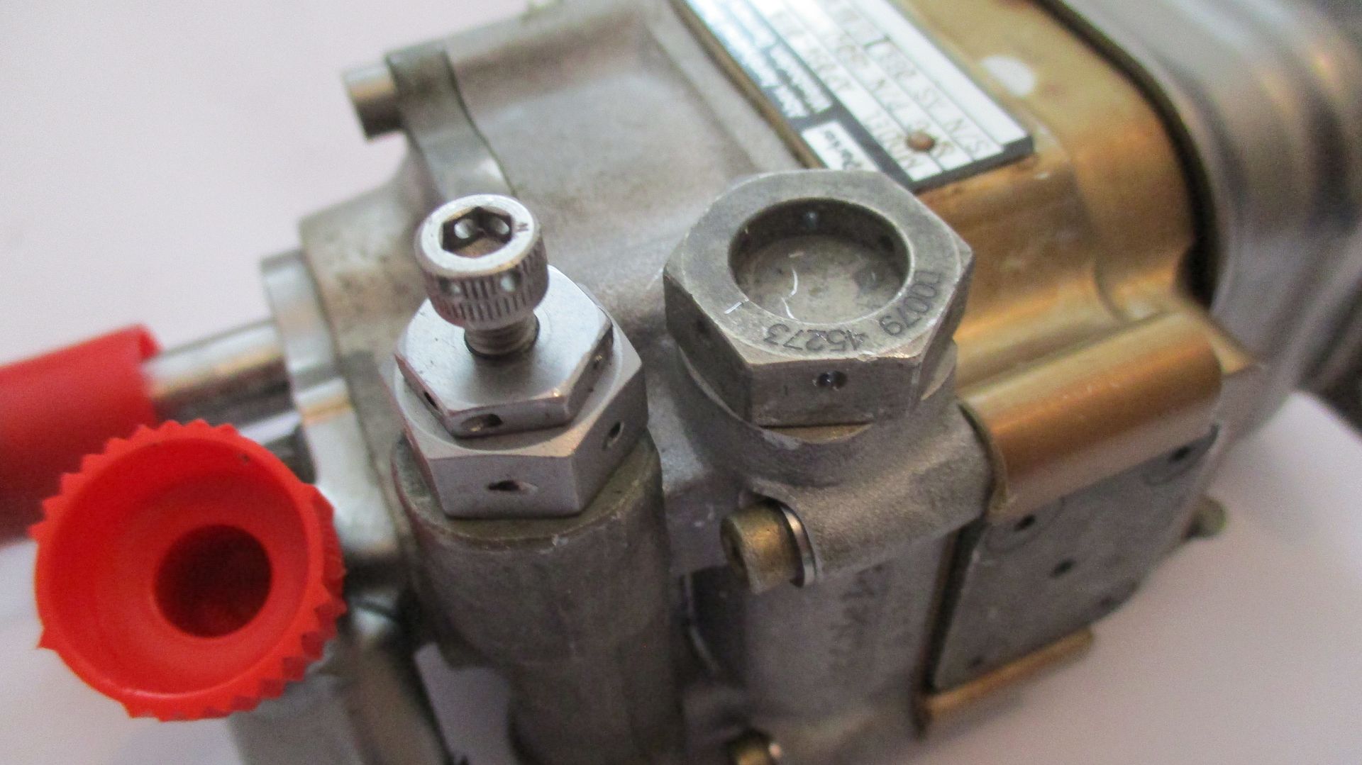
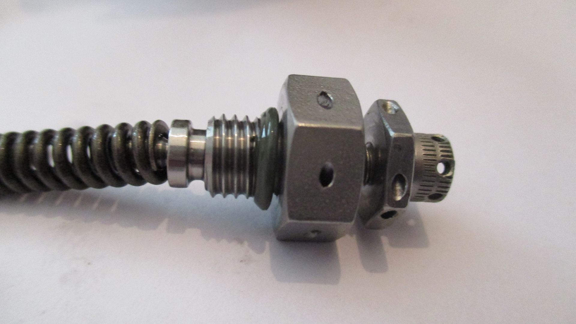
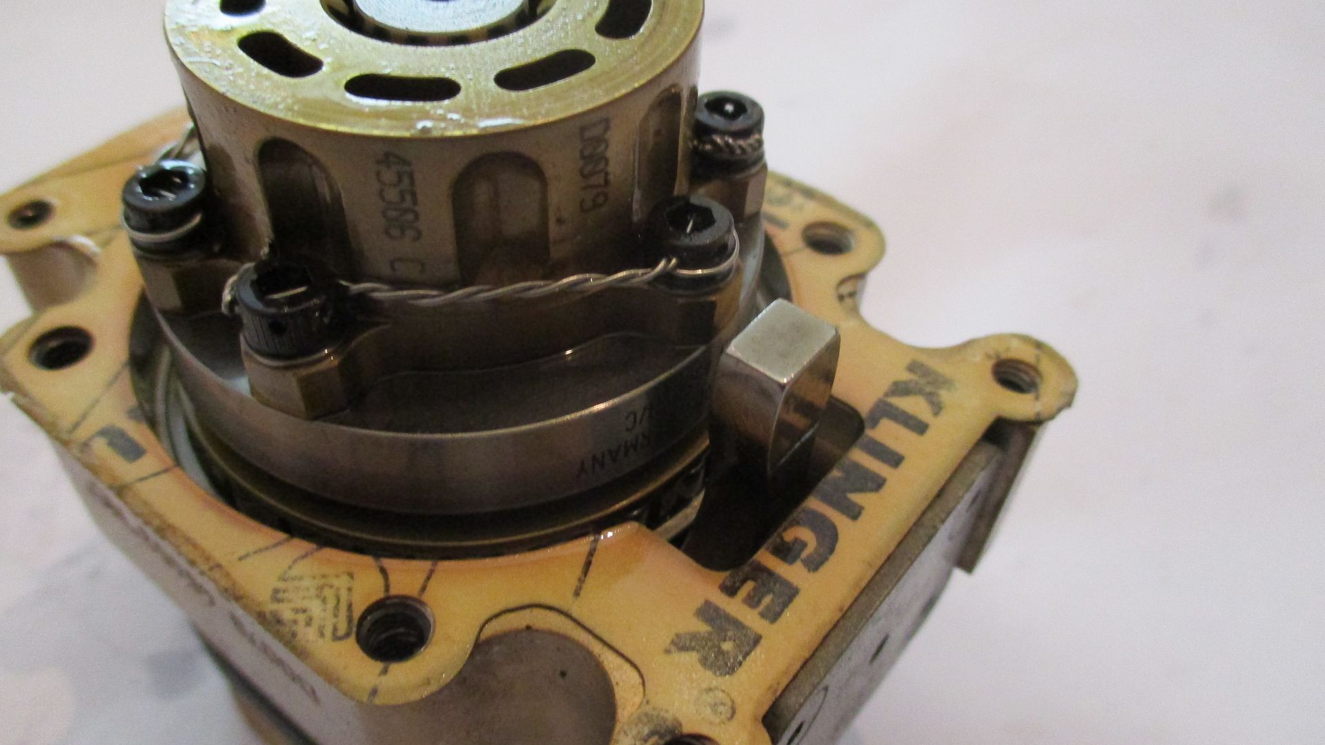
Lock wire detail - pressure adjustment screw on right, swash plate spring return cap nut on left,
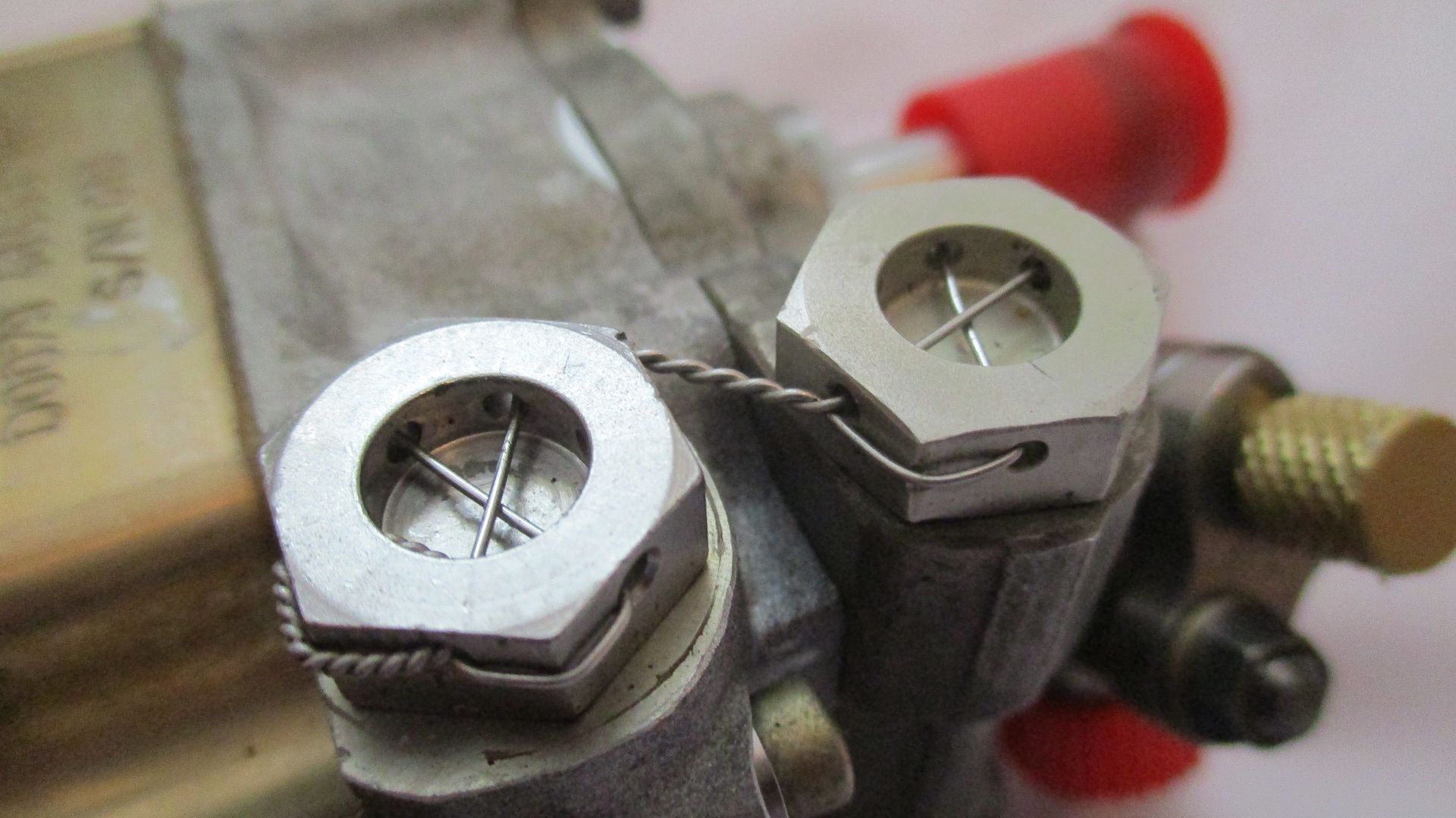
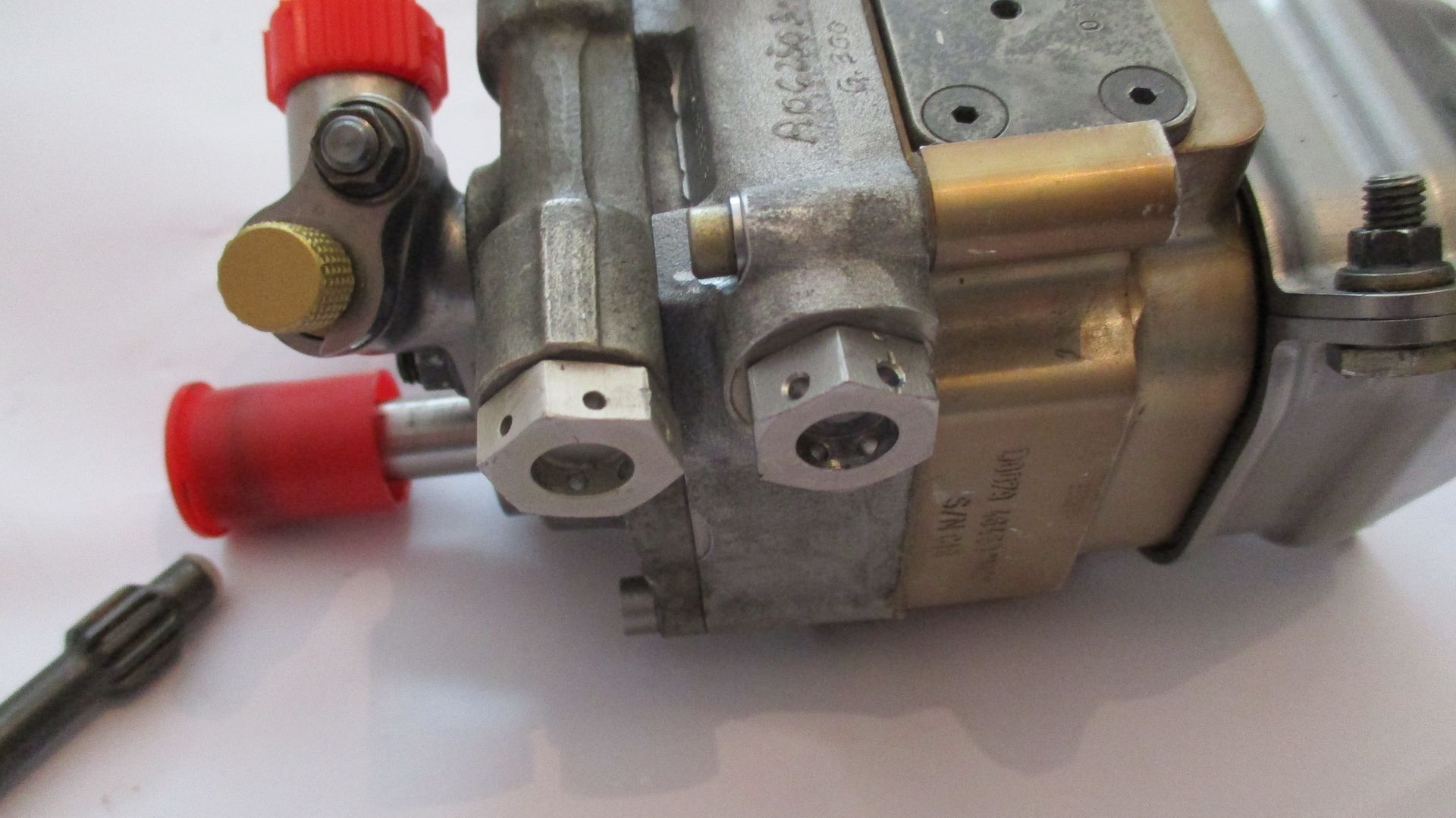
Opposite side,
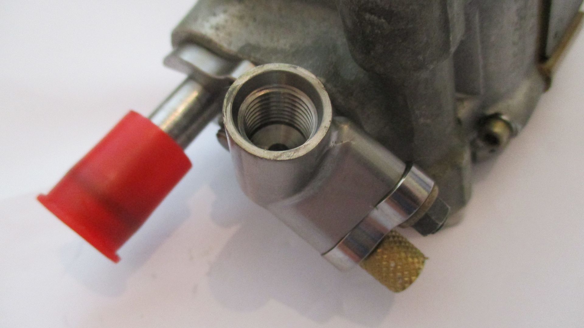
Fluid entry,
Fluid exit,
Lock wire removed,
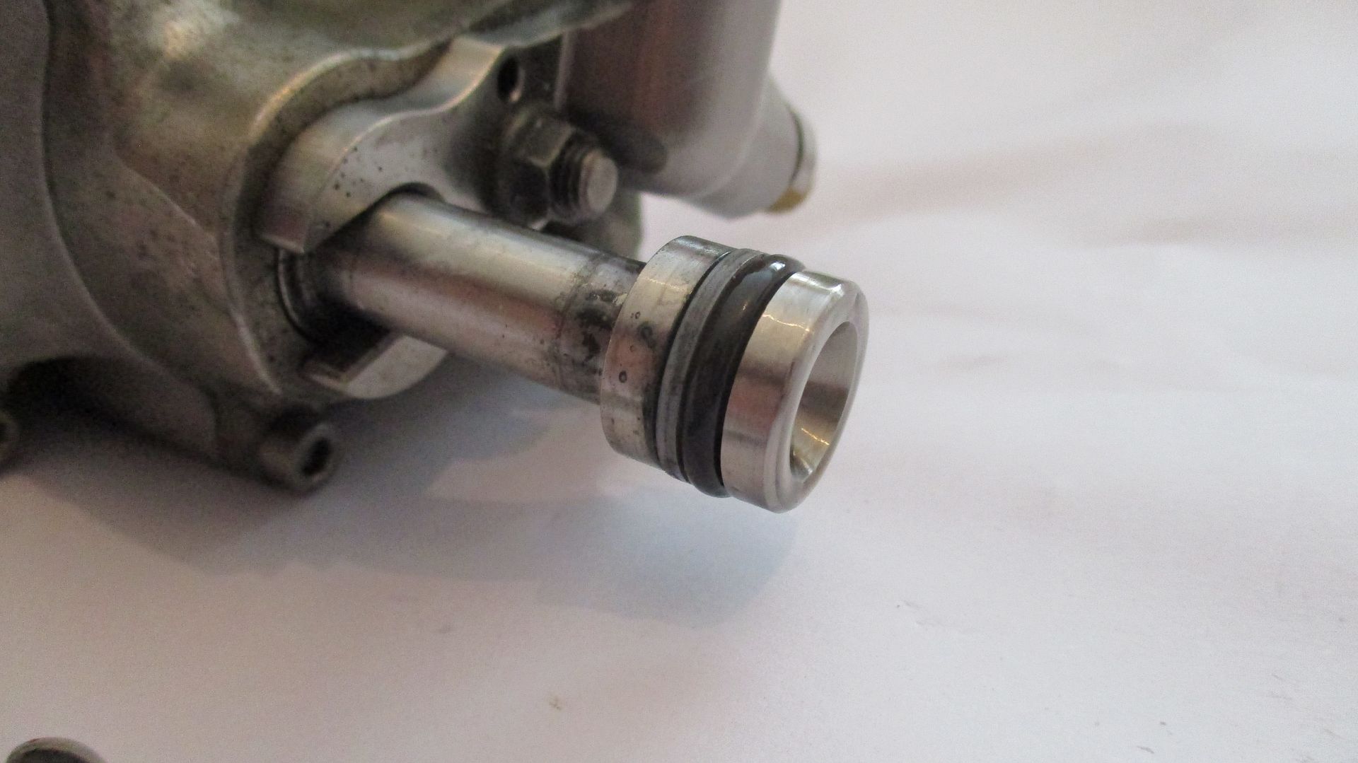
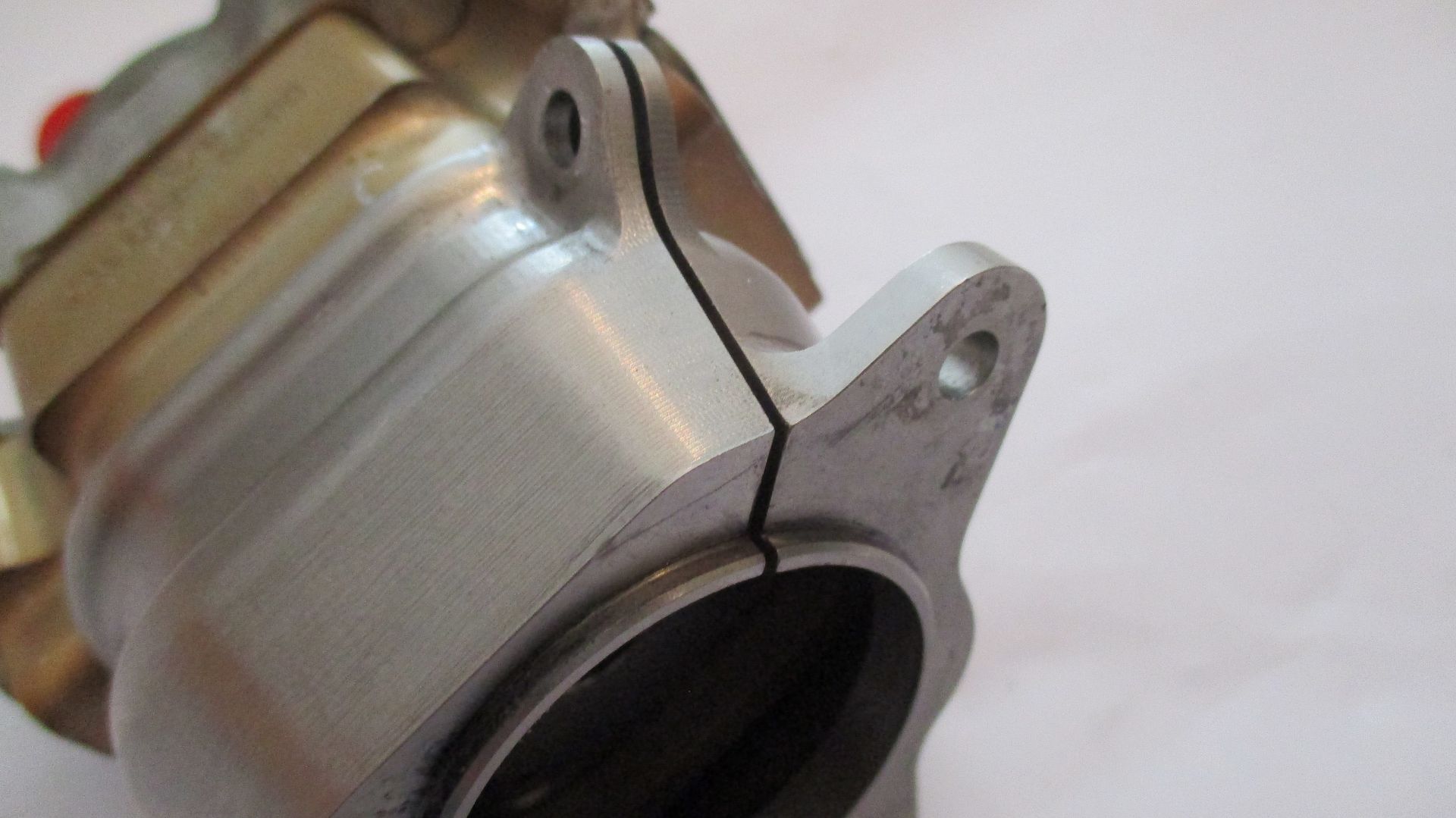
Mount flange removal, the mount flange clamps on two O-rings to provide dampening,
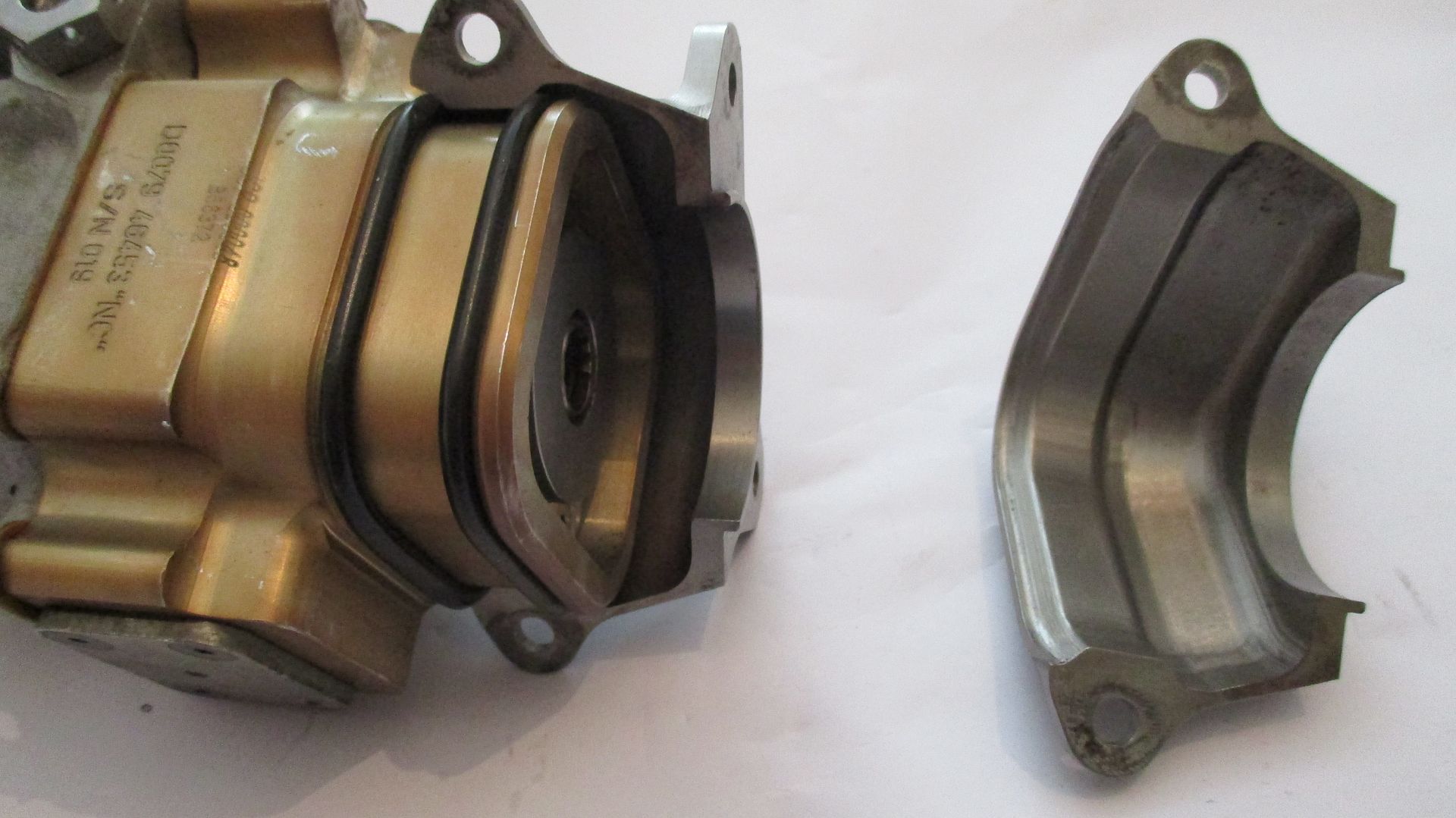
Removal of tail section which contains the pressure relief valve assembly - held on with titanium cap screws,
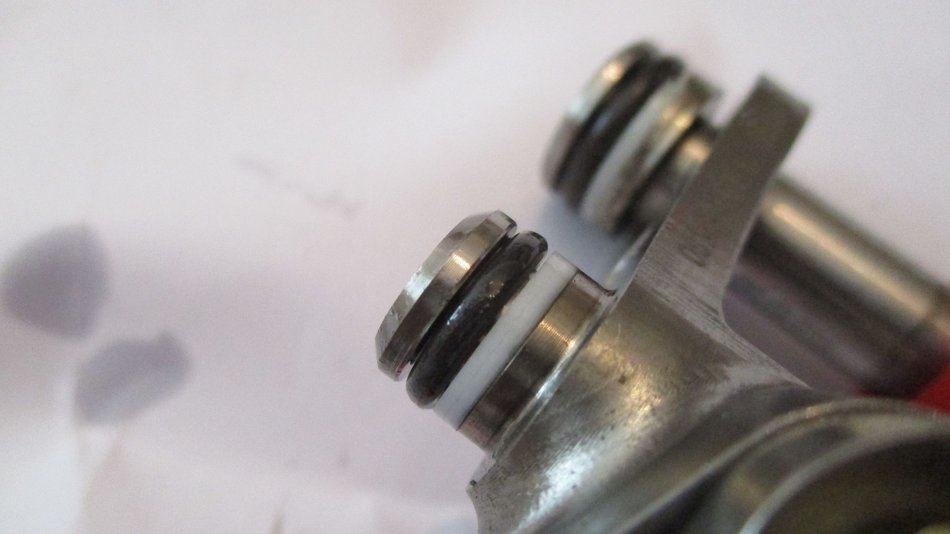
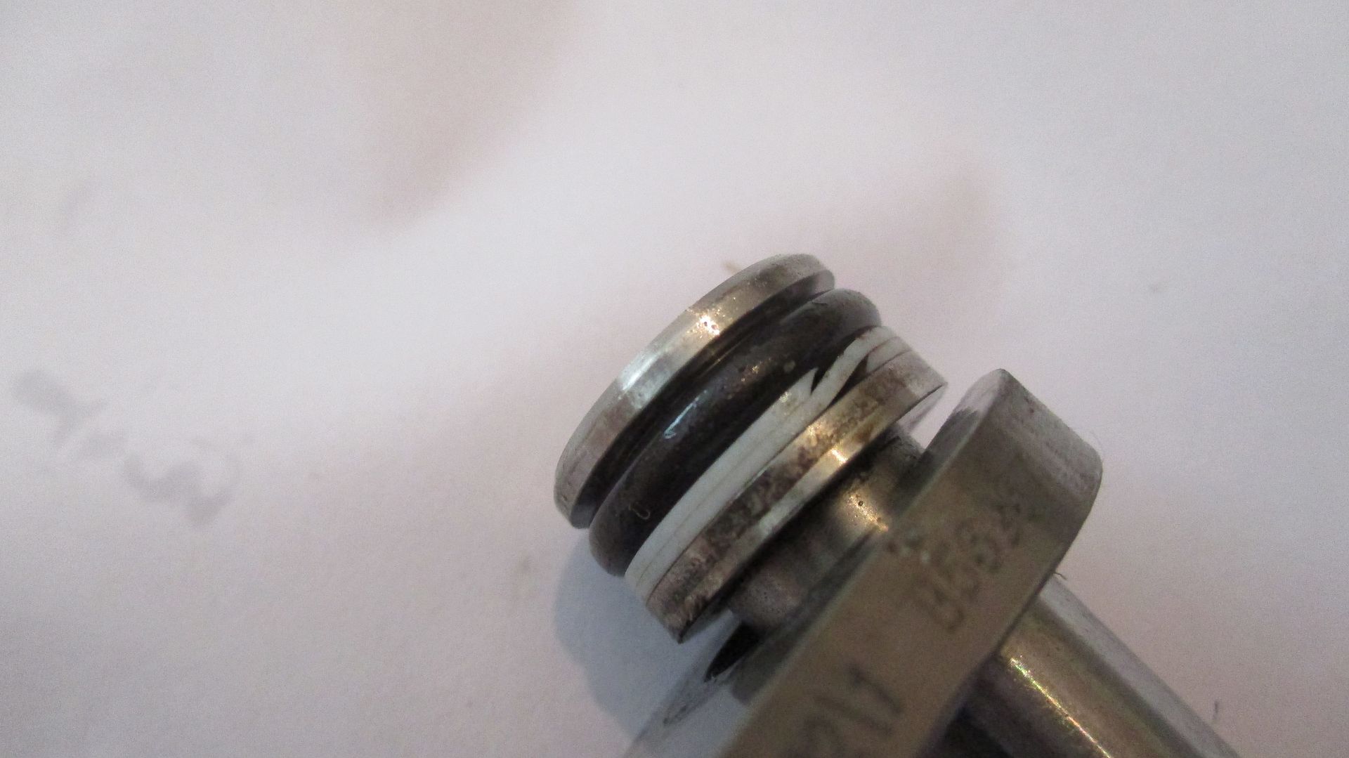
Seal details - O-ring with backup ring,
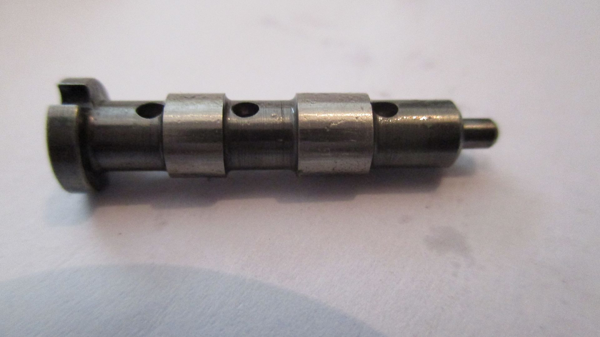
Removal of pressure bypass assembly from tail section - note spool type pressure control valve on left in 2nd picture and also the exit drilling from tail section pressure path which feeds into swash plate control piston,
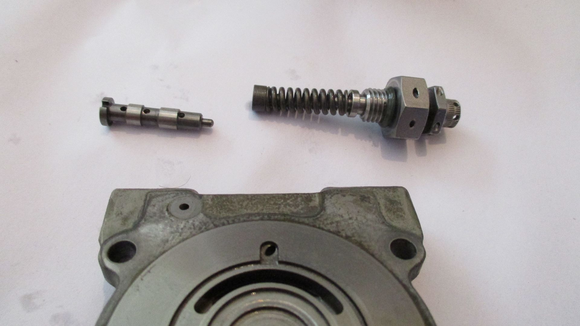
The concave button which sits on end of spool valve,
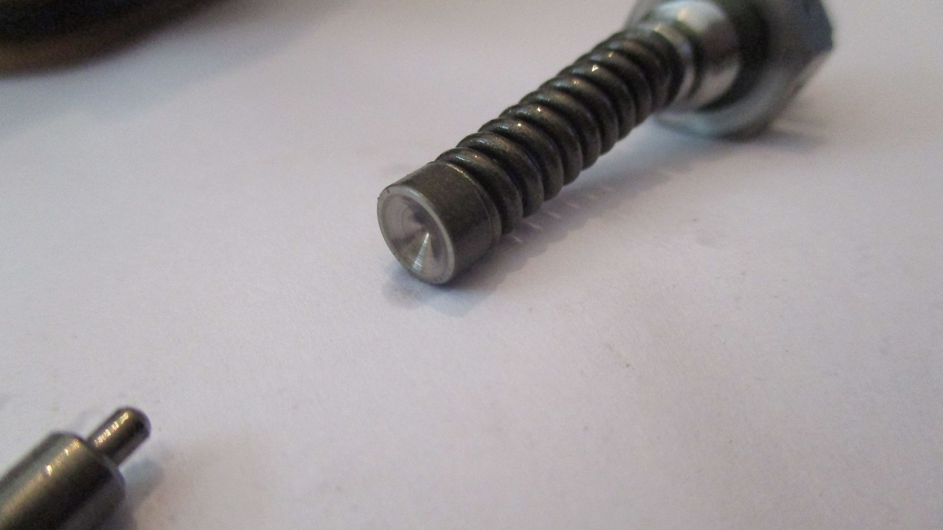
The pressure release spool valve up close - note the sliding pin in this valve is just 2mm in diameter,
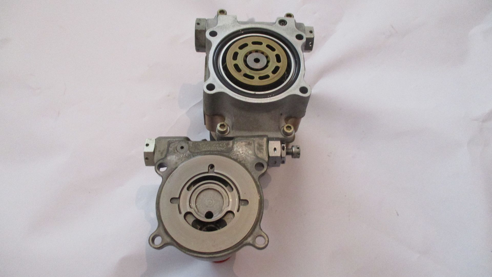
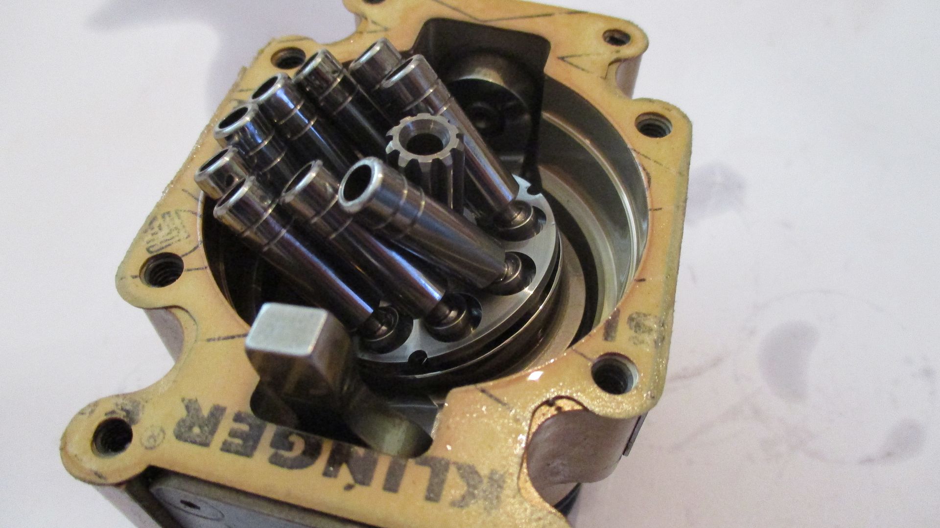
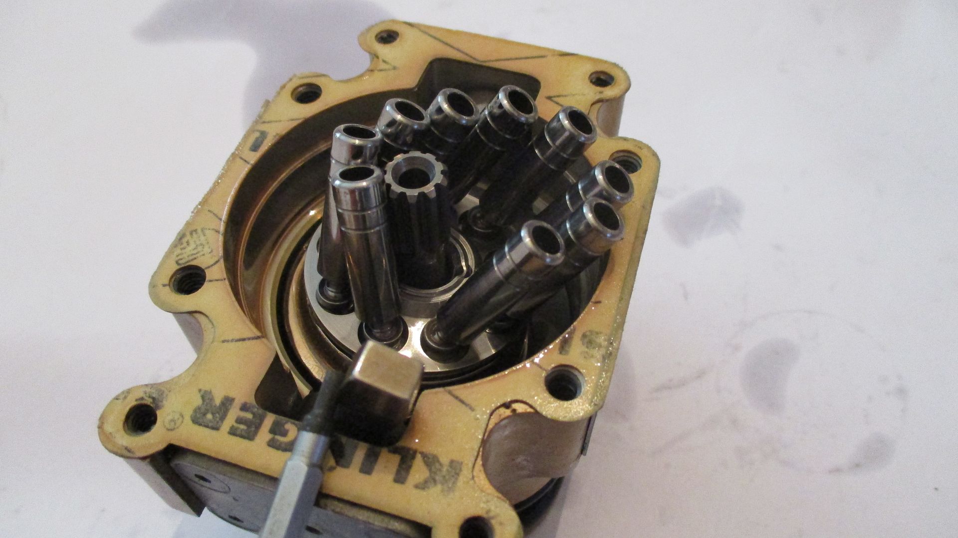
The face of the tail housing showing fluid entry and exit ports,
The face of the spinning axial piston chamber assembly - entry drilling for swash plate piston control top right,
Cast aluminium swash plate piston control body removed,
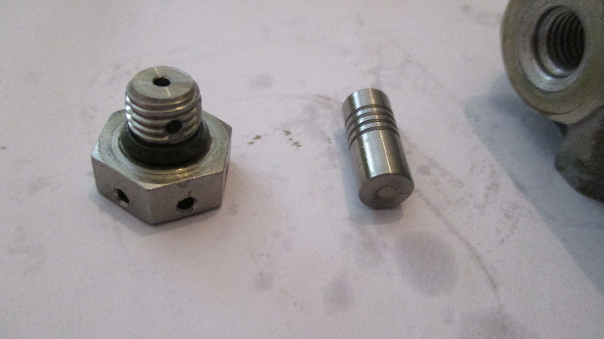
Swash plate control piston on left - sprung return plunger on right,
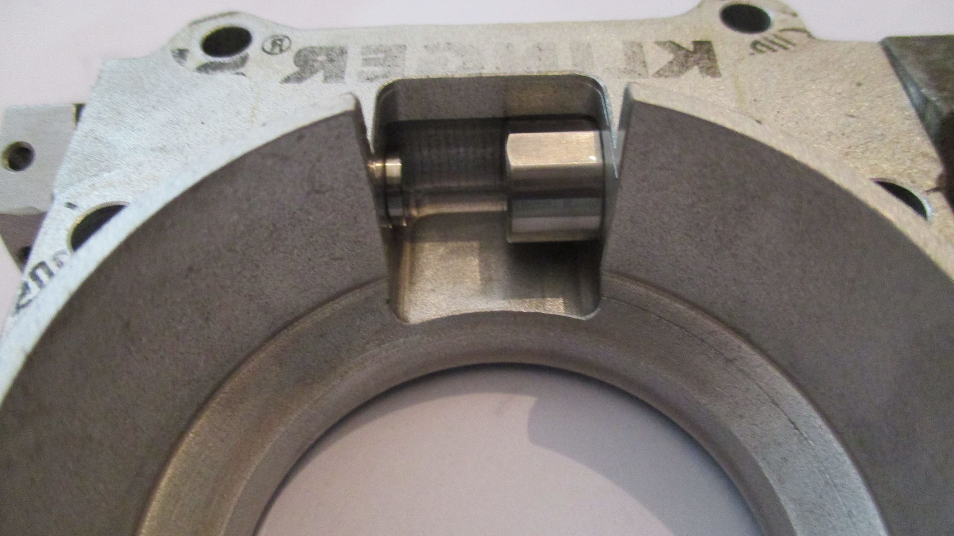
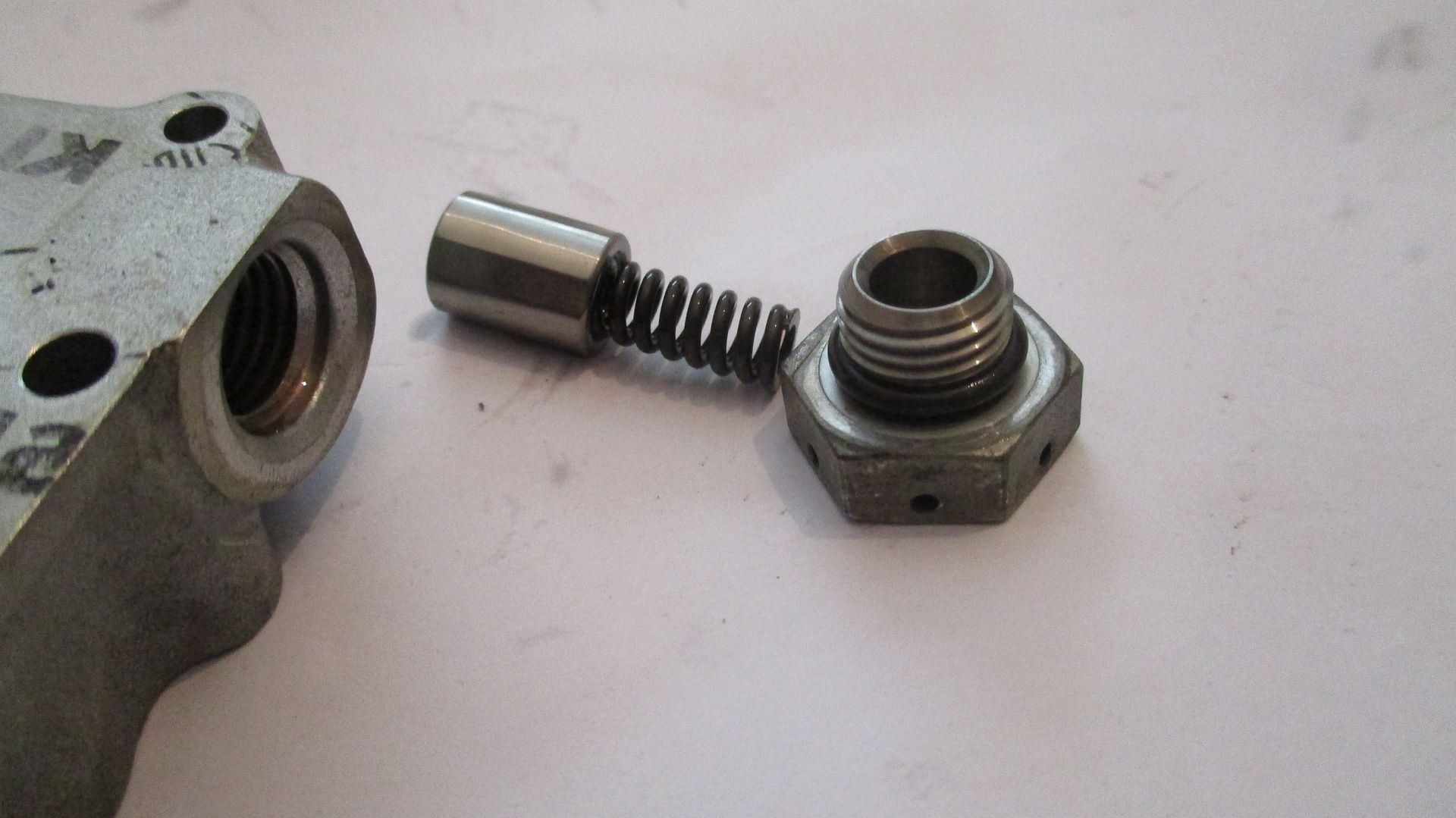
Control piston removed - oil enters into the side of the retaining banjo style bolt and exits the end - forcing the piston across to move forged swash plate carrier,
The tab on the swash plate carrier which the pistons above press on,
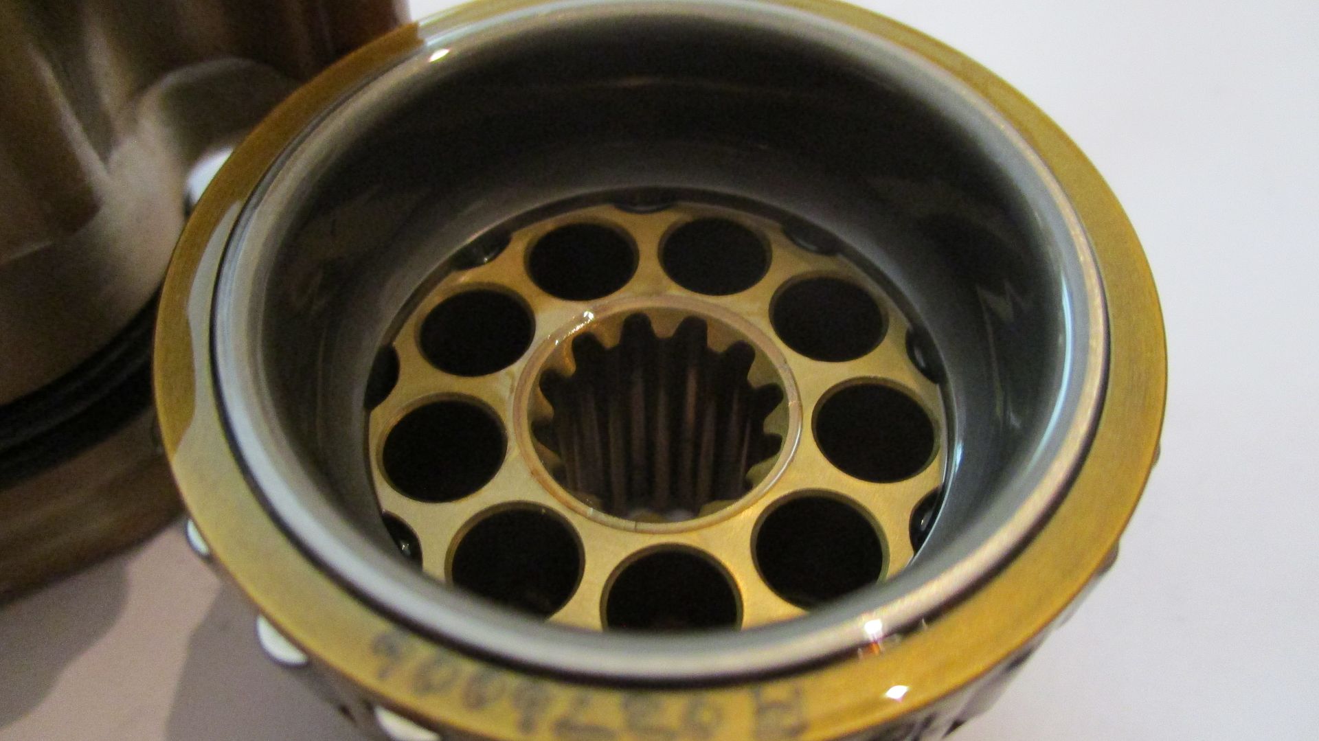
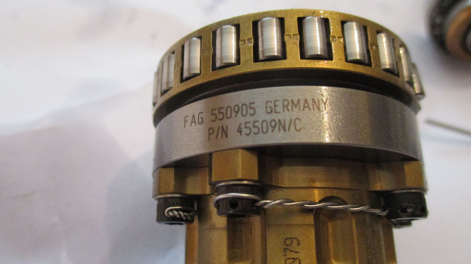
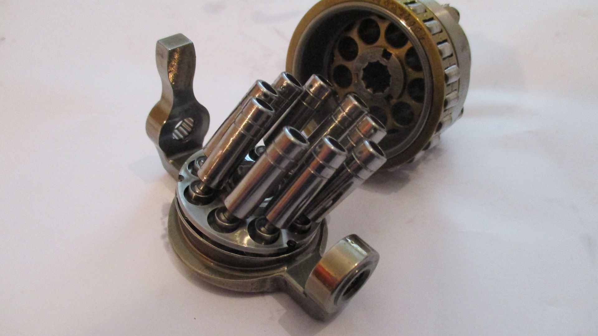
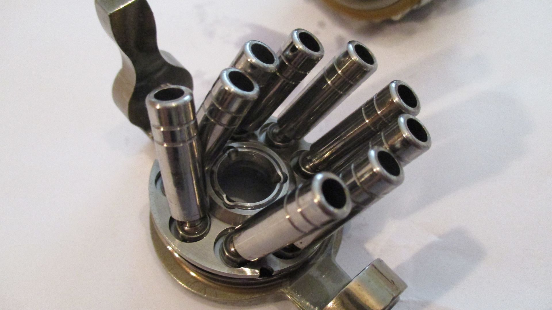
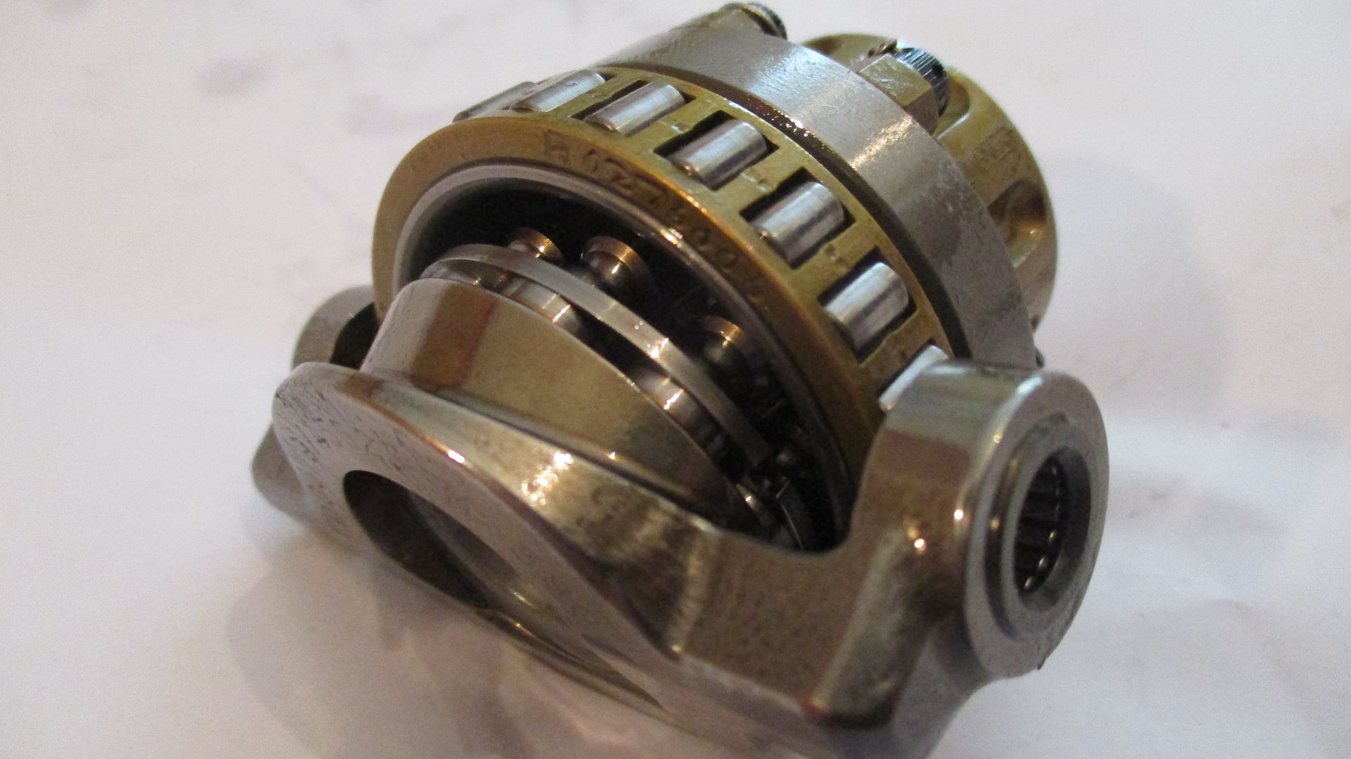
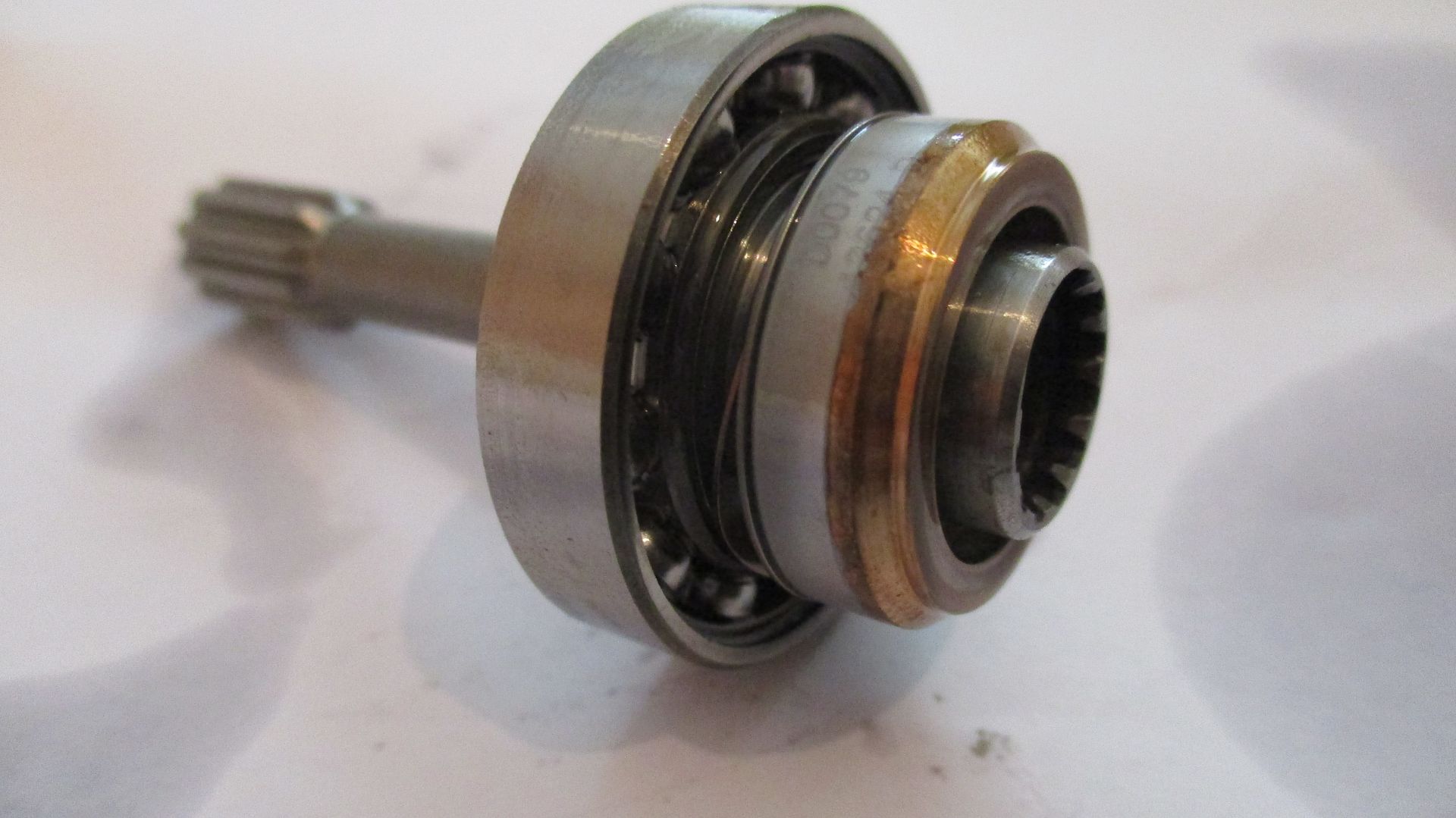
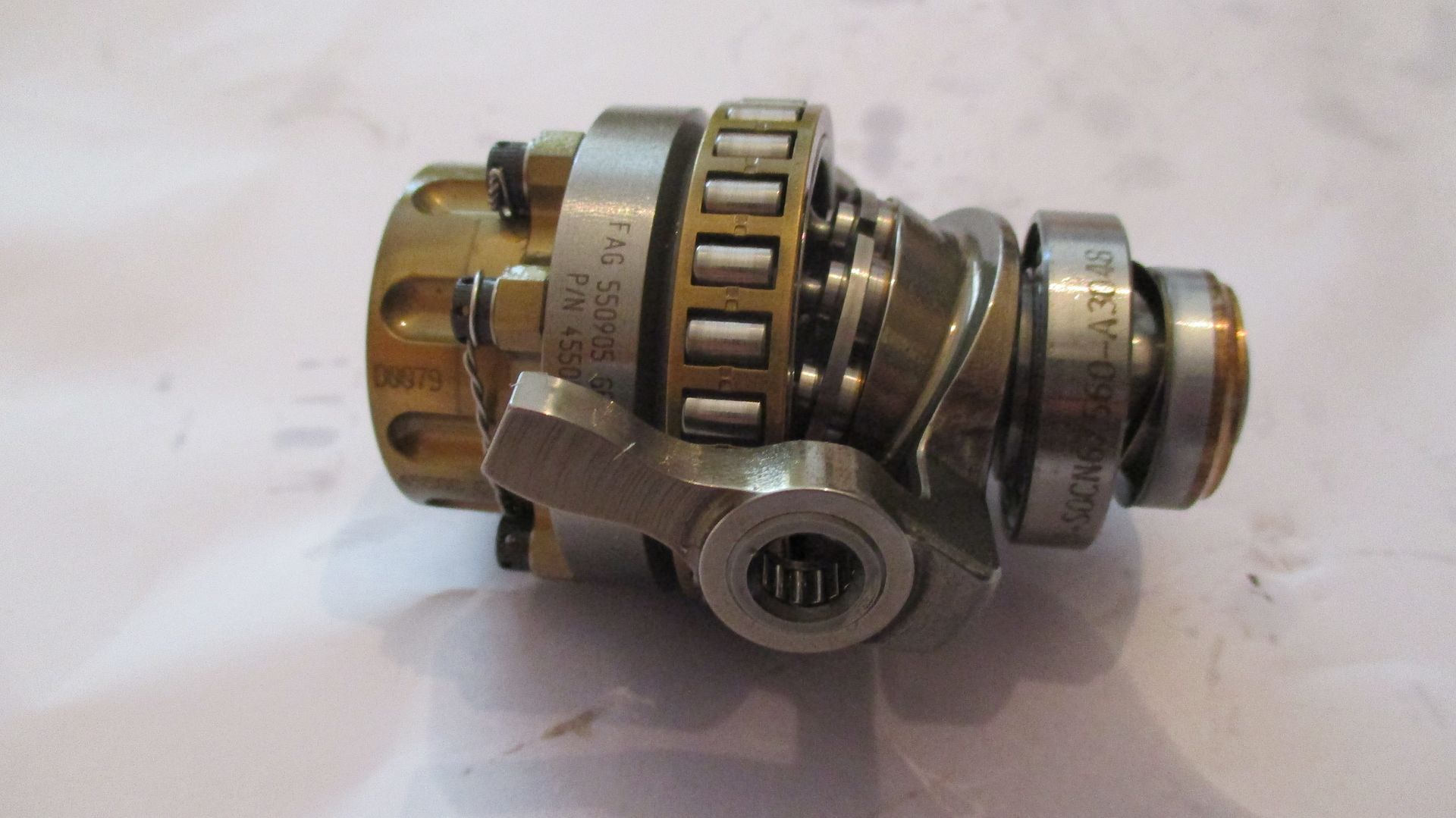
Axial piston chamber assembly removed,
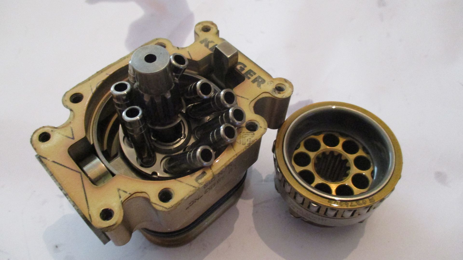
Spline detail as well as bearing detail - most of this assembly is bearing - only the gold part is piston chamber assembly. Worth noting - it is the piston chamber that is driven - this in turn then causes the pistons to rotate on the swash plate carrier,
Swash plate carrier pivot,
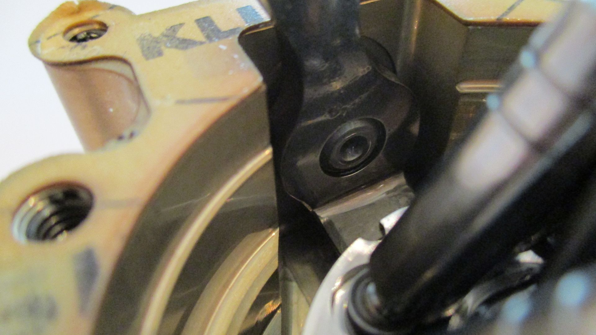
Swash plate carrier movement,
Removal of swash plate assembly, pivot plates hold carrier captive,
Pivot plate refitted for clarity,
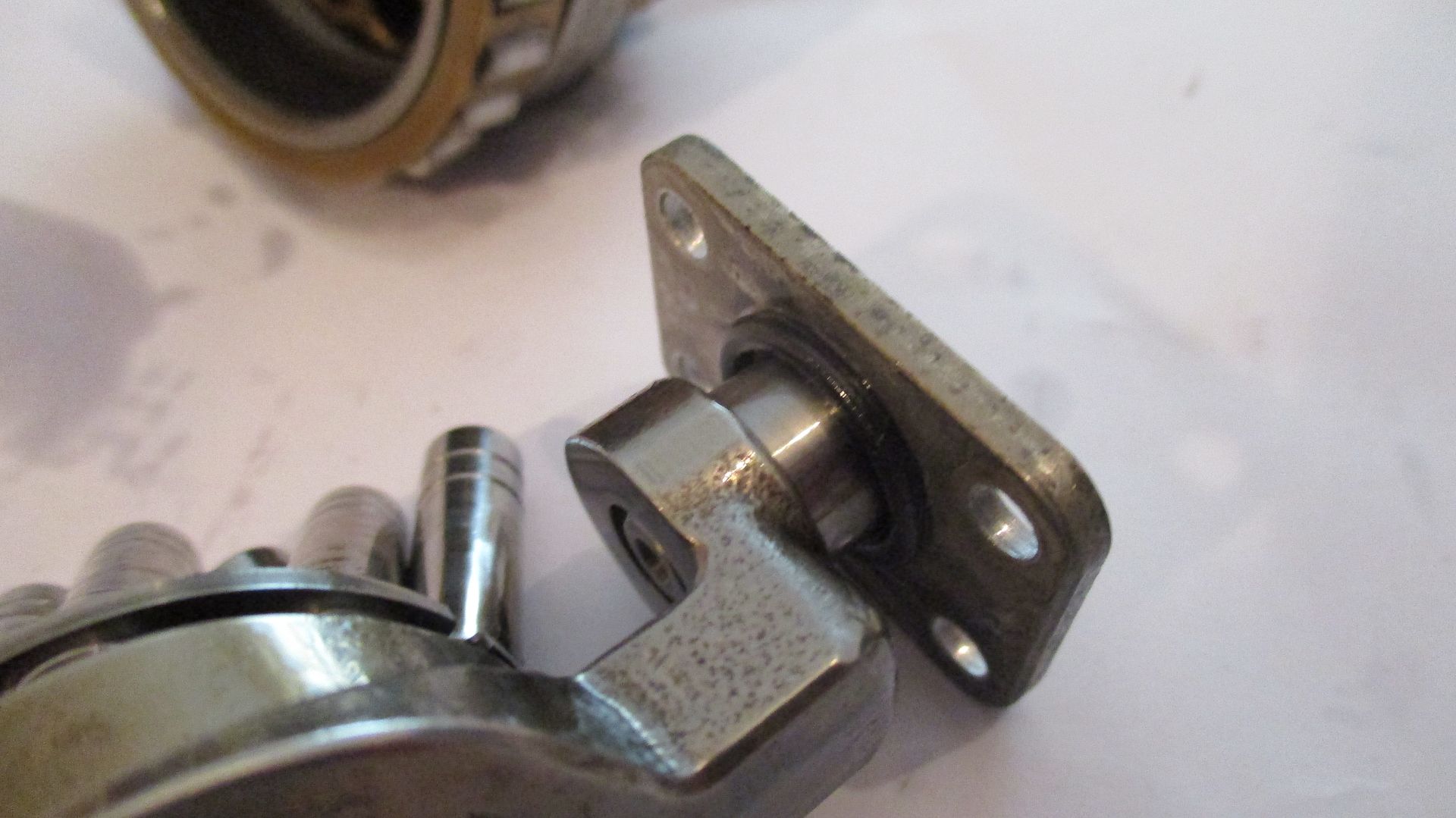
These locate onto needle bearings in the swash plate carrier,
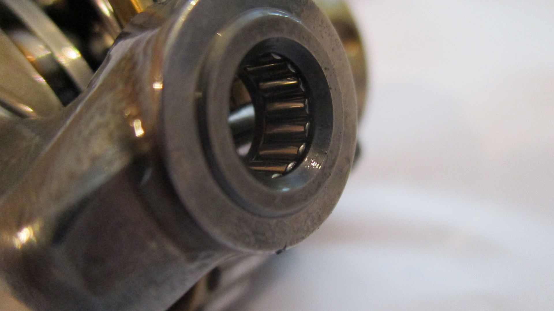
The outer race refitting into housing as it was difficult to see with the assembly installed,
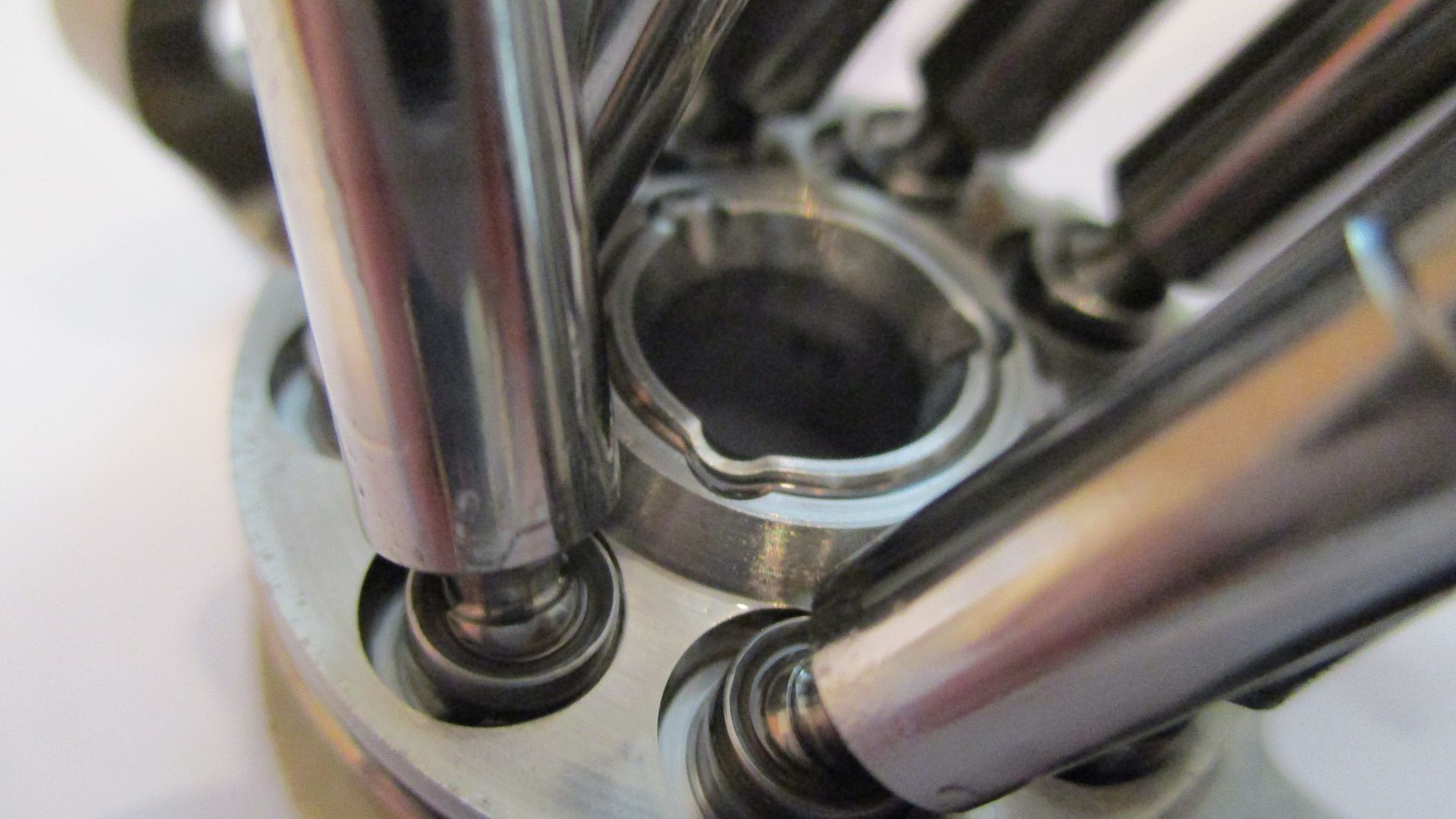
The swash plate and carrier fork refitted to pump piston body - the carrier fork is forged steel and incorporates an integral swash plate bearing thrust face,

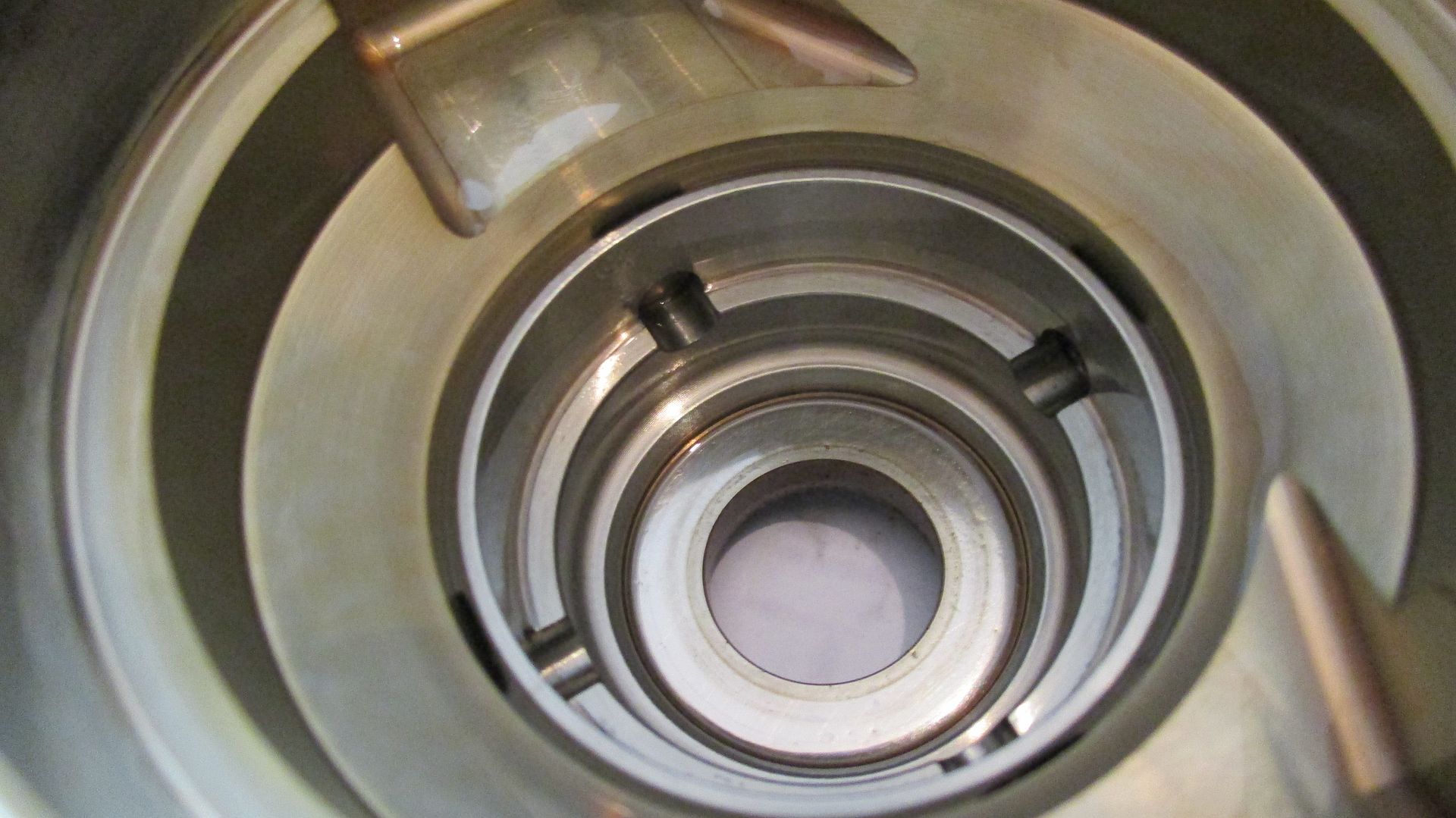
Interior - notice the notches internally to fit a tool to support when assembling the bearing parts,
On the opposite side, notches are also present for assembly as seen below,
Once seated, the nut plate is staked in 3 places,
A diagram below shows the fluid path in order to create the hydrodynamic oil film within the assembly,
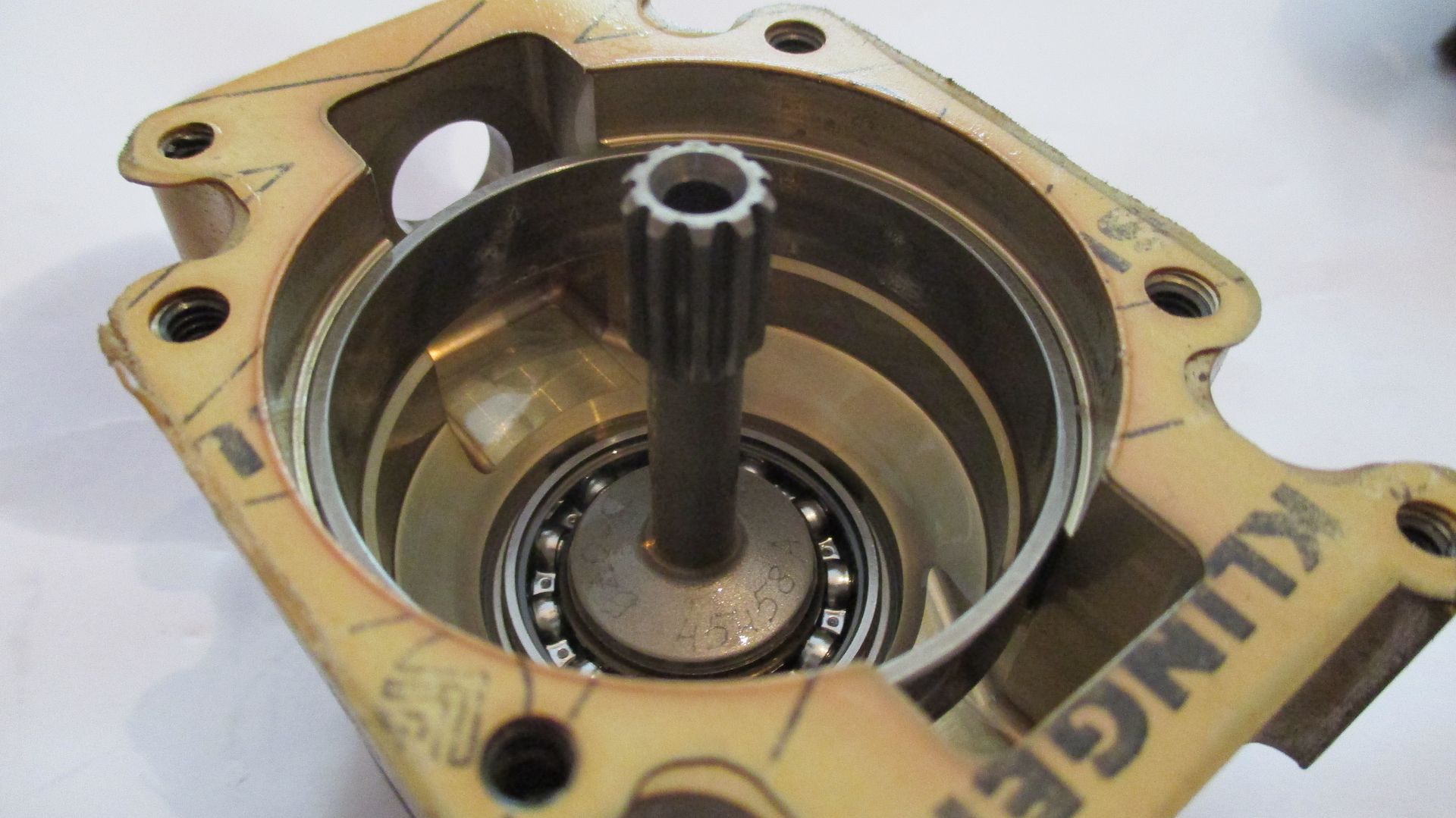
A shot of the main body and bearing,
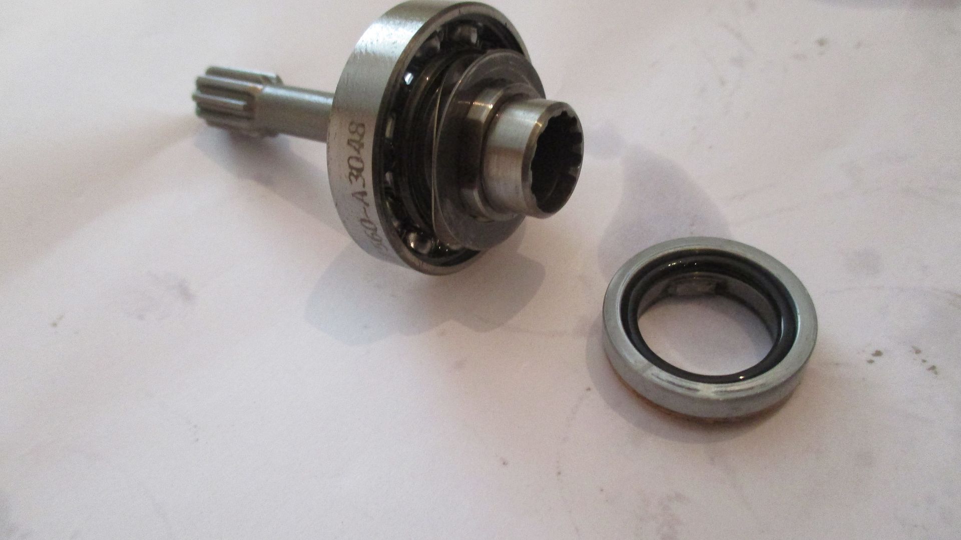
Drive shaft removed,
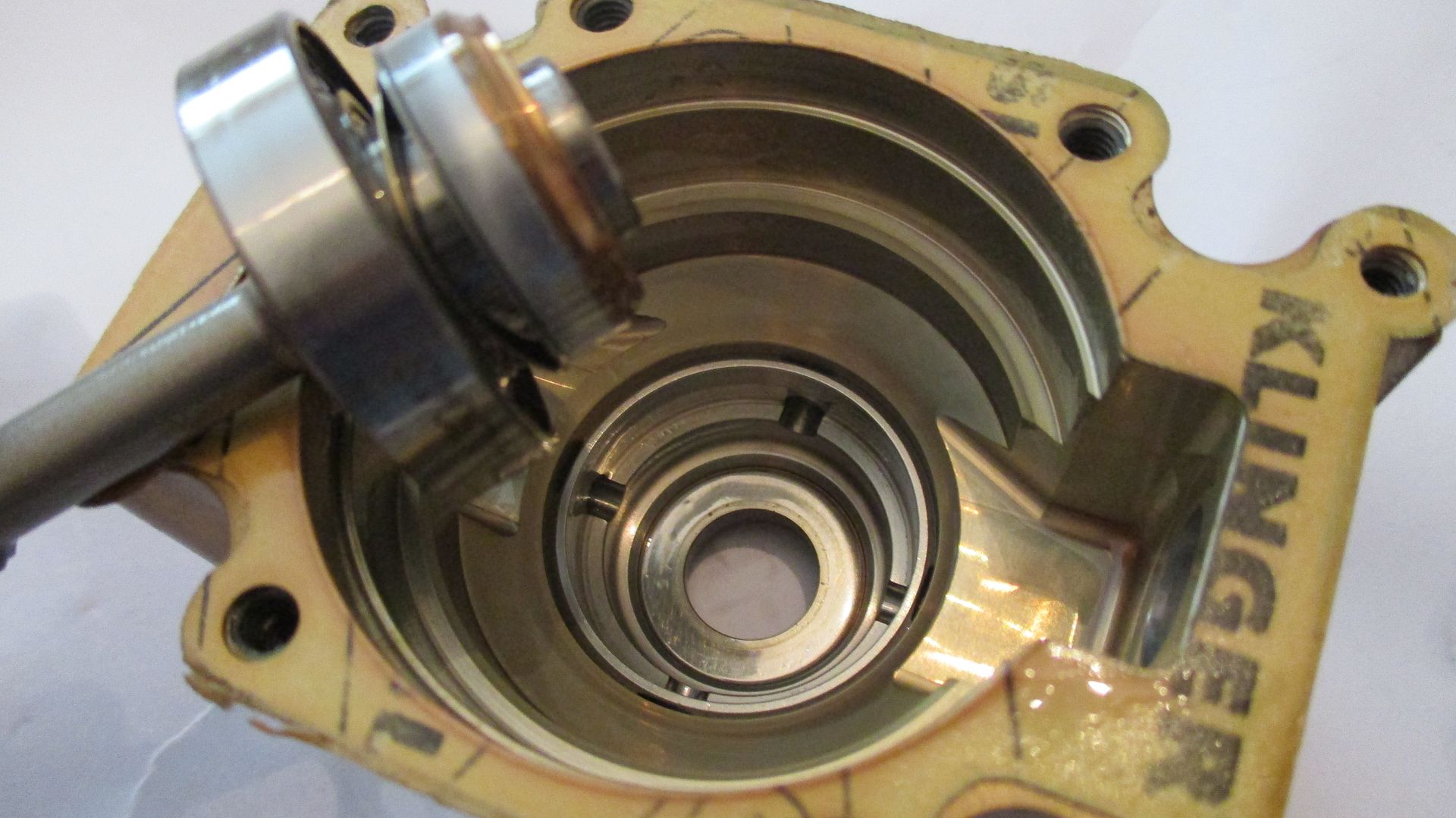
The seal arrangement - the metal part is spring loaded with a wave washer against the inside of main case,
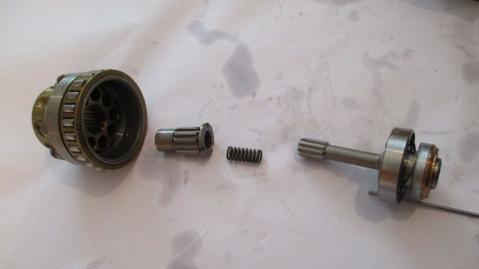
The assembled pump and parts,
Exploded shows how end float and drive is arranged - the spring at the end of the splined drive socket keeps the piston chamber assembly forced against the intake/Output port tail section.
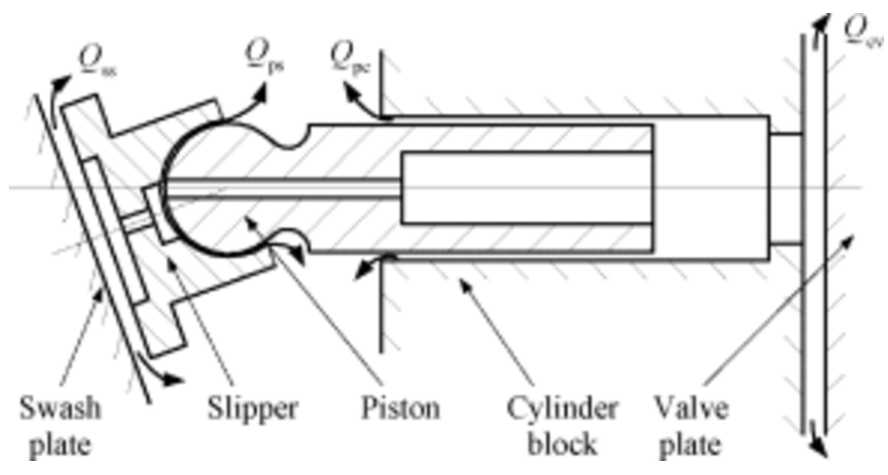
A simplified diagram of how the pump works for those not familiar,

(Image Courtesy of Michael Frey)
A 3d model of the pump above,
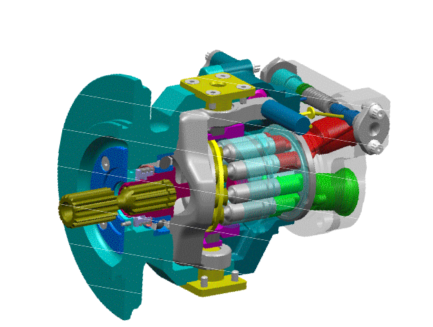
(Image Courtesy of Parker Aero Division)
So thats pretty much it in terms of what the F1 Hydraulic Pump looks like externally and internally - neat piece of kit and pretty important given the fact that it supplies fluid to pretty much everything critical on an F1 Car.
Until next time,
Brian,