Ferrari Power Unit Hardware & Software

All that has to do with the power train, gearbox, clutch, fuels and lubricants, etc. Generally the mechanical side of Formula One.
saviour stivala
51
Joined: 25 Apr 2018, 12:54

Re: Ferrari Power Unit Hardware & Software

Post

wuzak wrote:
24 Sep 2019, 04:13
Not many tracks in F1 where full power is used continuously for 18s.
Yes, in theory full power for 18 seconds of the lap could be used on all tracks, but in real racing it is not for a variety of reasons. Engine life. In a race, greatly depends on how close the attacking car behind is because of the need to save some to defend. The ability to fully charge by harvesting in the remaining time above the time spend using full power in a lap. But all this consideration/restrictions doesn’t apply to qualifying, as in qualifying neither the battery/ES discharging nor fuel consumed will influence the next lap. and moderator permitting for moving a bit off topic, this ability to deploy full power for the maximum time permitted by battery/ES SOC, during a lap and the ability to fully recharge for the rest of time during the lap, is one part of the FERRARI power advantage, the other part is played by the best combustion in use. at least this is my personal opinion.

User avatar
henry
324
Joined: 23 Feb 2004, 20:49
Location: England

Re: Ferrari Power Unit Hardware & Software

Post

Zynerji wrote:
24 Sep 2019, 04:52
I would expect a Q lap would be 4MJ from Batt->K, and running the H in pulsed harvest mode once minimum necessary "boost" is achieved, dumping all harvest energy directly to the K.

So, K max/lap = 4MJ batt + over harvest of H.

Can someone correct that if I'm mistaken, plz?
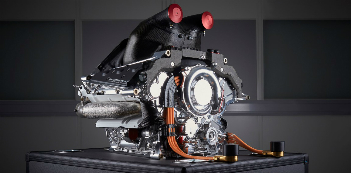
It’s much more complex than that. There are potentially 9 or 10 different basic combinations of ICE and ERS, I think of these as modes. These modes are knitted together by the strategy software during a lap to give the best lap time. As others have pointed out above the ES is filled or emptied during these modes at different rates. Say, for example, drained at 200kW in electric supercharge mode, drained at 60kW in self sustain plus, K driven by ES and H, charged at 120kW during braking. And so on, with other modes playing their part. Pulsed harvest is one such mode.

This means that in a qualification lap the ES will start at 4MJ and end at 0 but in between it may well process another 3 or 4 MJ driving the H with the excess charge it can’t send to the K. Likewise the K can receive 6 or 7 MJ with up to 4 from the ES and the rest from the H.

From a Ferrari performance perspective I concur with @Mattchu:
Mattchu wrote:
23 Sep 2019, 23:49

I personally think Ferrari potentially have a much better/more efficient MGUH system and this is what is giving them their power advantage. They don`t seem to have as much of a cooling issue as some teams [opening up bodywork, etc], maybe this is a clue they can use the heat generated better.
Chapeau to them, they`ve sure built a cracker which also seems to be very reliable.
Because of the way the modes interact small improvements in each element, such as H output, get magnified in overall performance.
Fortune favours the prepared; she has no favourites and takes no sides.
Truth is confirmed by inspection and delay; falsehood by haste and uncertainty : Tacitus

Tommy Cookers
617
Joined: 17 Feb 2012, 16:55

Re: Ferrari Power Unit Hardware & Software

Post

saviour stivala wrote:
22 Sep 2019, 22:31
Tommy Cookers wrote:
22 Sep 2019, 22:05
,,, Wright showed their engines had essentially the same mean exhaust pressure above and below the turbines
ie there was no 'back pressure'
There was also not only no waste-gates to run the engine with waste-gates open but also the full exhaust gasses produced by combustion of six cylinders pumping in each of the three turbines connected to the crankshaft.
ok imo the quote above is saying that in electric supercharge + wastegate the F1 turbine .....
sees only 25% of the exhaust mass ?
because the wastegate passes 75% of the mass in dropping the exhaust pressure from eg 4 bar abs to 1 bar abs ?

I think the turbine sees maybe 75% of the exhaust mass ... because ....
motoring H to high rpm reduces the turbine's load on the exhaust - substantially dropping the exhaust pressure (vs. eg 4 bar)
(eg if the turbine became disconnected from the H + compressor wouldn't the exhaust pressure fall close to 1 bar abs ?)
plus permissible total csa of the wastegate pipes is much smaller than permissible total csa of the exhaust pipe
Last edited by Tommy Cookers on 24 Sep 2019, 14:49, edited 3 times in total.

ENGINE TUNER
25
Joined: 29 Nov 2016, 18:07

Re: Ferrari Power Unit Hardware & Software

Post

Zarathustra wrote:
23 Sep 2019, 20:22
Would it be possible to create a ‘flow’ through the battery- plus have it discharge at the same time?
Highly inefficient, the battery is the most inefficient link in the chain.

Tommy Cookers
617
Joined: 17 Feb 2012, 16:55

Re: Ferrari Power Unit Hardware & Software

Post

Zarathustra wrote:
23 Sep 2019, 20:22
Would it be possible to create a ‘flow’ through the battery- plus have it discharge at the same time?
why not ?
wouldn't direct current conduction through electrolyte be more efficient than transmission via the charge/discharge cycle ?

User avatar
henry
324
Joined: 23 Feb 2004, 20:49
Location: England

Re: Ferrari Power Unit Hardware & Software

Post

Tommy Cookers wrote:
24 Sep 2019, 14:39
Zarathustra wrote:
23 Sep 2019, 20:22
Would it be possible to create a ‘flow’ through the battery- plus have it discharge at the same time?
why not ?
wouldn't direct current conduction through electrolyte be more efficient than transmission via the charge/discharge cycle ?
I’m not sure how that would work. There is only 1 connection to the ES so in and out have to be time division multiplexed. I don’t see how a constant flow can be made.
Fortune favours the prepared; she has no favourites and takes no sides.
Truth is confirmed by inspection and delay; falsehood by haste and uncertainty : Tacitus

User avatar
Zarathustra
-3
Joined: 01 Jul 2019, 20:19
Location: Always on the move- never at one place.
Contact:

Re: Ferrari Power Unit Hardware & Software

Post

henry wrote:
24 Sep 2019, 15:01
Tommy Cookers wrote:
24 Sep 2019, 14:39
Zarathustra wrote:
23 Sep 2019, 20:22
Would it be possible to create a ‘flow’ through the battery- plus have it discharge at the same time?
why not ?
wouldn't direct current conduction through electrolyte be more efficient than transmission via the charge/discharge cycle ?
I’m not sure how that would work. There is only 1 connection to the ES so in and out have to be time division multiplexed. I don’t see how a constant flow can be made.
How are the H and K ‘joining’ in that single connection?

(Genuine question- I am a real noob, just trying to understand ‘things’ that are out of my league)

User avatar
henry
324
Joined: 23 Feb 2004, 20:49
Location: England

Re: Ferrari Power Unit Hardware & Software

Post

Zarathustra wrote:
24 Sep 2019, 15:15
henry wrote:
24 Sep 2019, 15:01
Tommy Cookers wrote:
24 Sep 2019, 14:39

why not ?
wouldn't direct current conduction through electrolyte be more efficient than transmission via the charge/discharge cycle ?
I’m not sure how that would work. There is only 1 connection to the ES so in and out have to be time division multiplexed. I don’t see how a constant flow can be made.
How are the H and K ‘joining’ in that single connection?

(Genuine question- I am a real noob, just trying to understand ‘things’ that are out of my league)
The H & K are not connected directly to the ES. They connect to the Control Electronics. It is the CE which has a single connection to the ES which is where all the measurements are taken to ensure rules related to the ES electrical performance are obeyed.
Fortune favours the prepared; she has no favourites and takes no sides.
Truth is confirmed by inspection and delay; falsehood by haste and uncertainty : Tacitus

User avatar
MtthsMlw
1033
Joined: 12 Jul 2017, 18:38
Location: Germany

Re: Ferrari Power Unit Hardware & Software

Post

henry wrote:
24 Sep 2019, 16:22
Zarathustra wrote:
24 Sep 2019, 15:15
henry wrote:
24 Sep 2019, 15:01


I’m not sure how that would work. There is only 1 connection to the ES so in and out have to be time division multiplexed. I don’t see how a constant flow can be made.
How are the H and K ‘joining’ in that single connection?

(Genuine question- I am a real noob, just trying to understand ‘things’ that are out of my league)
The H & K are not connected directly to the ES. They connect to the Control Electronics. It is the CE which has a single connection to the ES which is where all the measurements are taken to ensure rules related to the ES electrical performance are obeyed.
I know there is the CE between them but on pictures of the Merc PU the ES has two connections.
Or do these two go to the CE first?
Image

User avatar
dans79
267
Joined: 03 Mar 2013, 19:33
Location: USA

Re: Ferrari Power Unit Hardware & Software

Post

MtthsMlw wrote:
24 Sep 2019, 16:37
I know there is the CE between them but on pictures of the Merc PU the ES has two connections.
Or do these two go to the CE first?
https://www.pmw-magazine.com/wp-content ... Resize.jpg
CE first. You can see it in the diagram from the technical regulations appendix.
197 104 103 7

Dr. Acula
46
Joined: 28 Jul 2018, 13:23

Re: Ferrari Power Unit Hardware & Software

Post

MtthsMlw wrote:
24 Sep 2019, 16:37
I know there is the CE between them but on pictures of the Merc PU the ES has two connections.
Or do these two go to the CE first?
https://www.pmw-magazine.com/wp-content ... Resize.jpg
The MGU-K, MGU-H and ES are all connected to the CE. The CE can transfer Energy from the MGU-H to the MGU-K and vise versa directly without the use of the battery.
Honda for instance uses this to get around the charge limit of the MGU-K->ES. They take the root MGU-K->MGU-H->ES sometimes. It's less efficient, but you can get over the cap of 2MJ per lap.

User avatar
henry
324
Joined: 23 Feb 2004, 20:49
Location: England

Re: Ferrari Power Unit Hardware & Software

Post

Even if the connection didn’t go through the CE the connection to the ES itself would be two wires, a “+ve” and a “-ve”.

I think the connections between the CE and the MGUs is AC with multiple wires as seen in the picture.
Fortune favours the prepared; she has no favourites and takes no sides.
Truth is confirmed by inspection and delay; falsehood by haste and uncertainty : Tacitus

Tommy Cookers
617
Joined: 17 Feb 2012, 16:55

Re: Ferrari Power Unit Hardware & Software

Post

the MGs aren't 'on-line' machines such as the public might expect
the 'control' electronics are better called 'drive' electronics
as they contain external to the electric machine's functional parts equivalent to functional parts that are internal to an ICE

that's why there's more than 2 wires
and there's a closed-loop control connection to a rotational position or timing sensor in the EM

User avatar
Zarathustra
-3
Joined: 01 Jul 2019, 20:19
Location: Always on the move- never at one place.
Contact:

Re: Ferrari Power Unit Hardware & Software

Post

henry wrote:
24 Sep 2019, 16:22
Zarathustra wrote:
24 Sep 2019, 15:15
henry wrote:
24 Sep 2019, 15:01


I’m not sure how that would work. There is only 1 connection to the ES so in and out have to be time division multiplexed. I don’t see how a constant flow can be made.
How are the H and K ‘joining’ in that single connection?

(Genuine question- I am a real noob, just trying to understand ‘things’ that are out of my league)
The H & K are not connected directly to the ES. They connect to the Control Electronics. It is the CE which has a single connection to the ES which is where all the measurements are taken to ensure rules related to the ES electrical performance are obeyed.
Thx!

User avatar
Mattchu
49
Joined: 07 Jul 2014, 19:37

Re: Ferrari Power Unit Hardware & Software

Post

Are there not 3 wires because the motor is 3 phase AC?

DC out of battery -> Invertor -> MGUK/H

Post Reply