Hello Tommy Cookers.
You write:
"regarding the previously-mentioned automatic adjustment of 'propeller' (or 'proprotor') pitch .....
isn't this what has been the normal way of propellers for 80 years ?
(how/why ?) is something desired beyond this existing range of capabilities ?
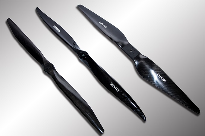
(as I said a year ago) today (for 'recreational' aircraft anyway) there's (some anyway) such capability without moving parts by suitably 'tailored' propeller structural properties available from use of composite materials
proper propeller maps seem irritatingly rare ..."
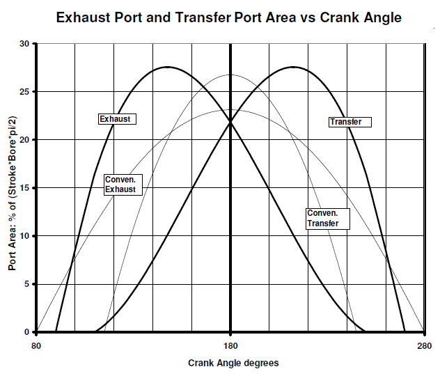
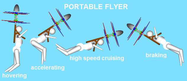
With propellers having 43" diameter / 15" pitch and spinning at 3,500rpm, the total static thrust of the Portable Flyer:
is more than 1000N (100Kg), while the required power by the engine(s) is about 30kW; however even with the propellers spinning at 4,500rpm, the maximum speed is limited at only 100Km/h.
In order the Portable Flyer to be able to cruise at 250Km/h, the required propeller pitch is nearly 40".
With 40" pitch, instead of 15" pitch, the power required by the engine(s) at hovering, take off and landing is overdoubled.
If the propeller pitch could be properly, and widely, adjusted to the operational conditions then, among others, the hovering duration, the top speed and the maximum take-off weight would substantially increase.
Here is a variable pitch propeller:
(slow motion at
https://www.pattakon.com/Pitch/PatPitch_2_slow.gif)
Spot on the blades that move slightly outwards when the propeller spins faster.
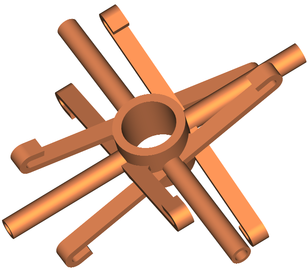
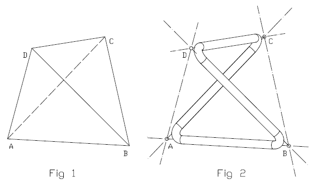
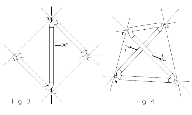
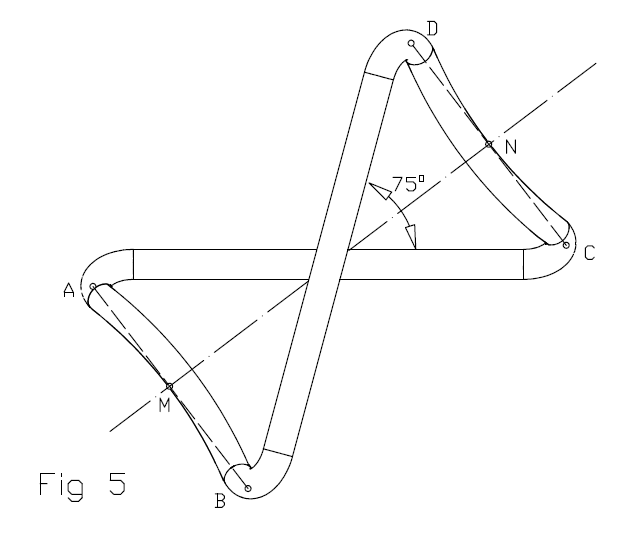
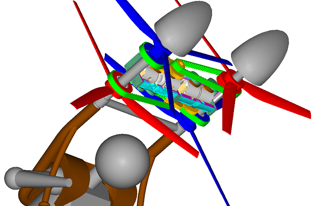
Here is another variable pitch propeller / rotor:
Each red wire-frame "forms" a
tetrahedron.
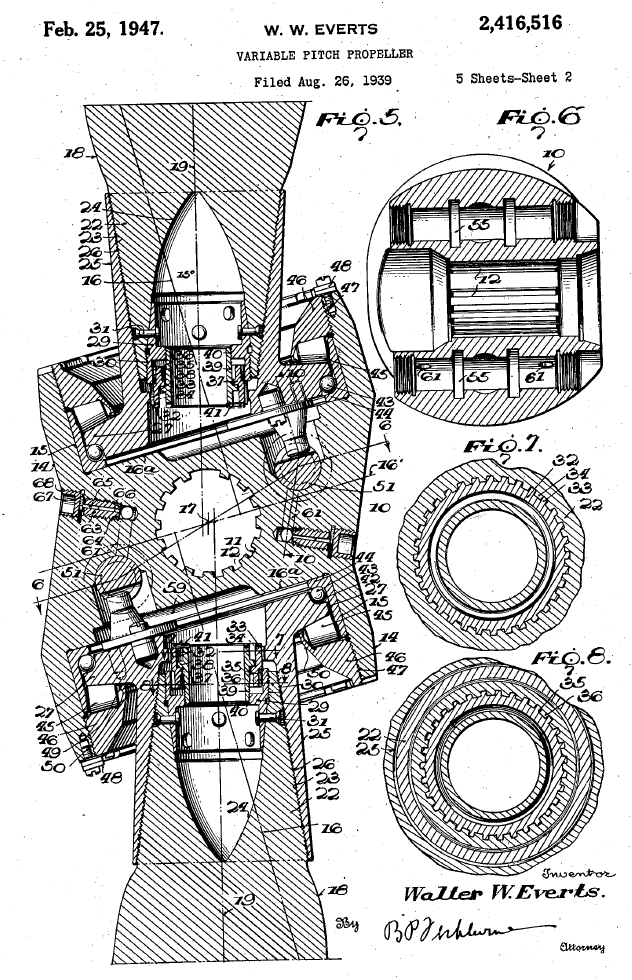
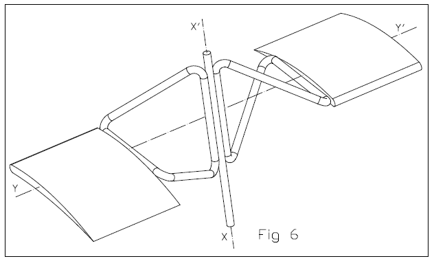
And here:
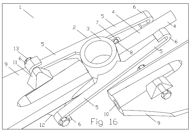
is apropeller / rotor comprising two blades and a hub.
The hub 2 comprises a center 3, two pins 4 and two pairs of flexible "skew" arms 5.
Each blade 9 has a hole / bearing 10 through which it is mounted on its respective pin 4 of the hub 2; each blade 9 has a pair of supports (like 11, 12 and 13), through which it is held by a pair of flexible "skew" arms 5.
The hub also comprises two stops 7, one per blade 9; the stop 7, with its bolt 8 prevents the respective blade from going to a pitch below a minimum; the stop also allows the preloading of the flexible arms.
At operation a shaft (or a sprocket, or a gearwheel etc) forces the propeller 1 to spin about a rotation axis. The blades 9 supported on respective pins 4 of the hub 2 are forced to follow the rotation of the hub about the rotation axis.
The centrifugal forces on the blades push them away from the rotation axis of the propeller; however the hooks 6 at the ends of the flexible arms 5 hold the blades 9 from moving away the rotation axis of the propeller.
Until an angular speed, the preloading of the flexible arms in combination with the stops ( 7 , 8 ) keep the blades at a minimum pitch.
Above an angular speed, the centrifugal force acting on each blade gets so strong that it pulls the blade slightly outwards (away from the propeller rotation axis), causing the bending of the flexible skew arms, which in turn causes the angular displacement of the blade about its long axis, which varies the pitch.
The higher the angular speed, the heavier the centrifugal force pulling each blade outwards, the larger the bending of the pair of flexible arms that hold the blade, the larger the angular displacement of the blade about its long axis (which, here, is the axis of the pin), and the bigger the pitch of the propeller.
With the pitch of the propellers of the Portable Flyer (first image in this post) being nearly 15" till 3,500rpm (of the propellers), with the pitch increasing to 40" at 4,000rpm (due to the centrifugal forces action) and to 45" above 4,500rpm (of the propellers) the power required from the engines lowers a lot, at emergency landings the healthy engine is not overloaded, the hovering duration extends a lot, the maximum speed goes beyond 300Km/h, etc, etc.
By the way:
Atan( 15" / (43" * pi) ) = 6.5 degrees,
Atan( 45" / (43" * pi) ) = 18.5 degrees.
I.e. each blade needs to turn for only 12 degrees about its long axis ( Y - Y' in Fig. 6 ) in order the pitch to increase from 15" to 45".
More at
https://www.pattakon.com/pattakonPitch.htm
Thanks
Manolis Pattakos