Mercedes V10 F1 Engine - Picture Thread

All that has to do with the power train, gearbox, clutch, fuels and lubricants, etc. Generally the mechanical side of Formula One.
Post Reply
63l8qrrfy6
368
Joined: 17 Feb 2016, 21:36

Re: Mercedes V10 F1 Engine - Picture Thread

Post

ACRO wrote: ↑
12 Aug 2020, 12:24
very good information , thank you much !!!

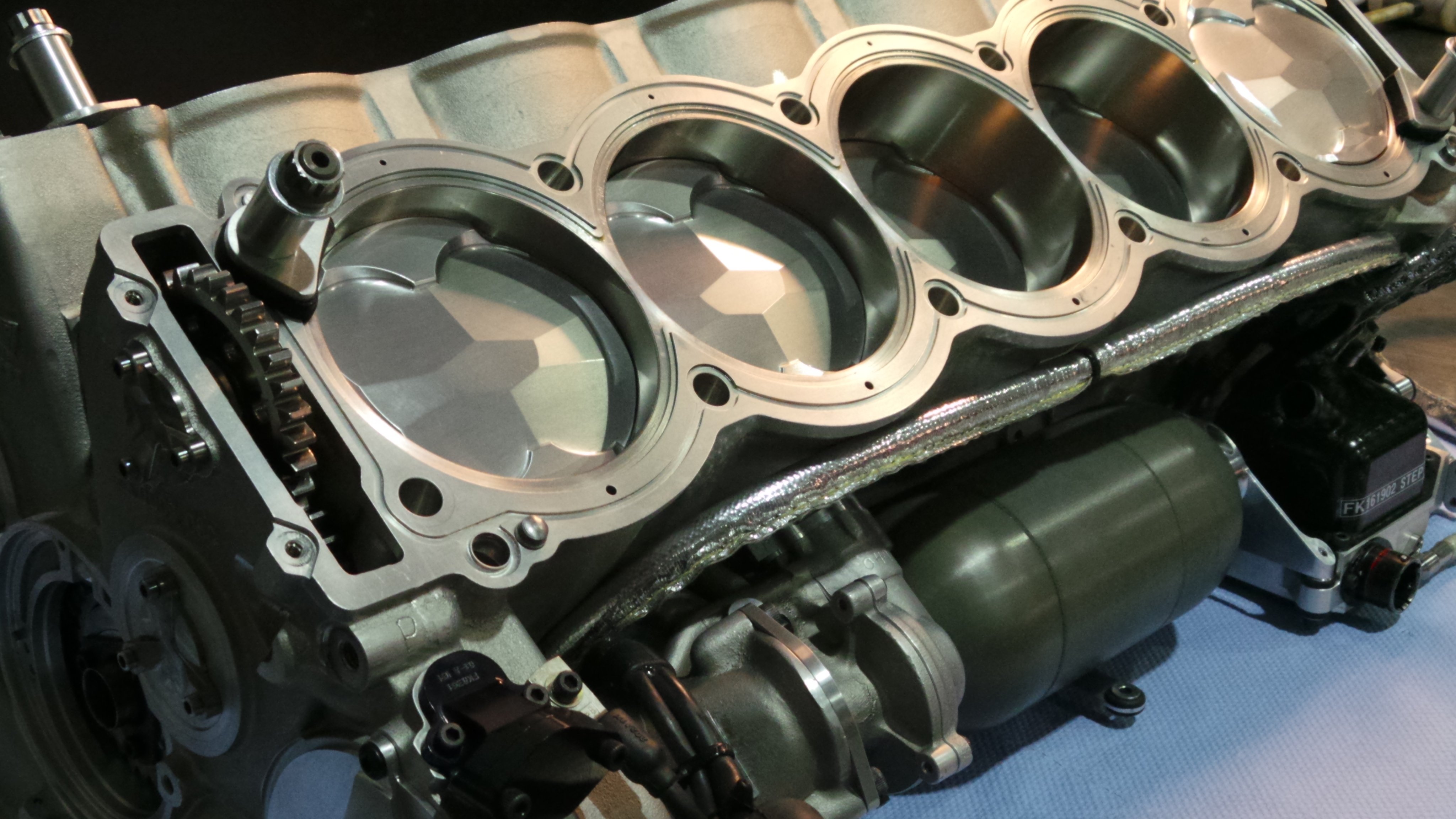
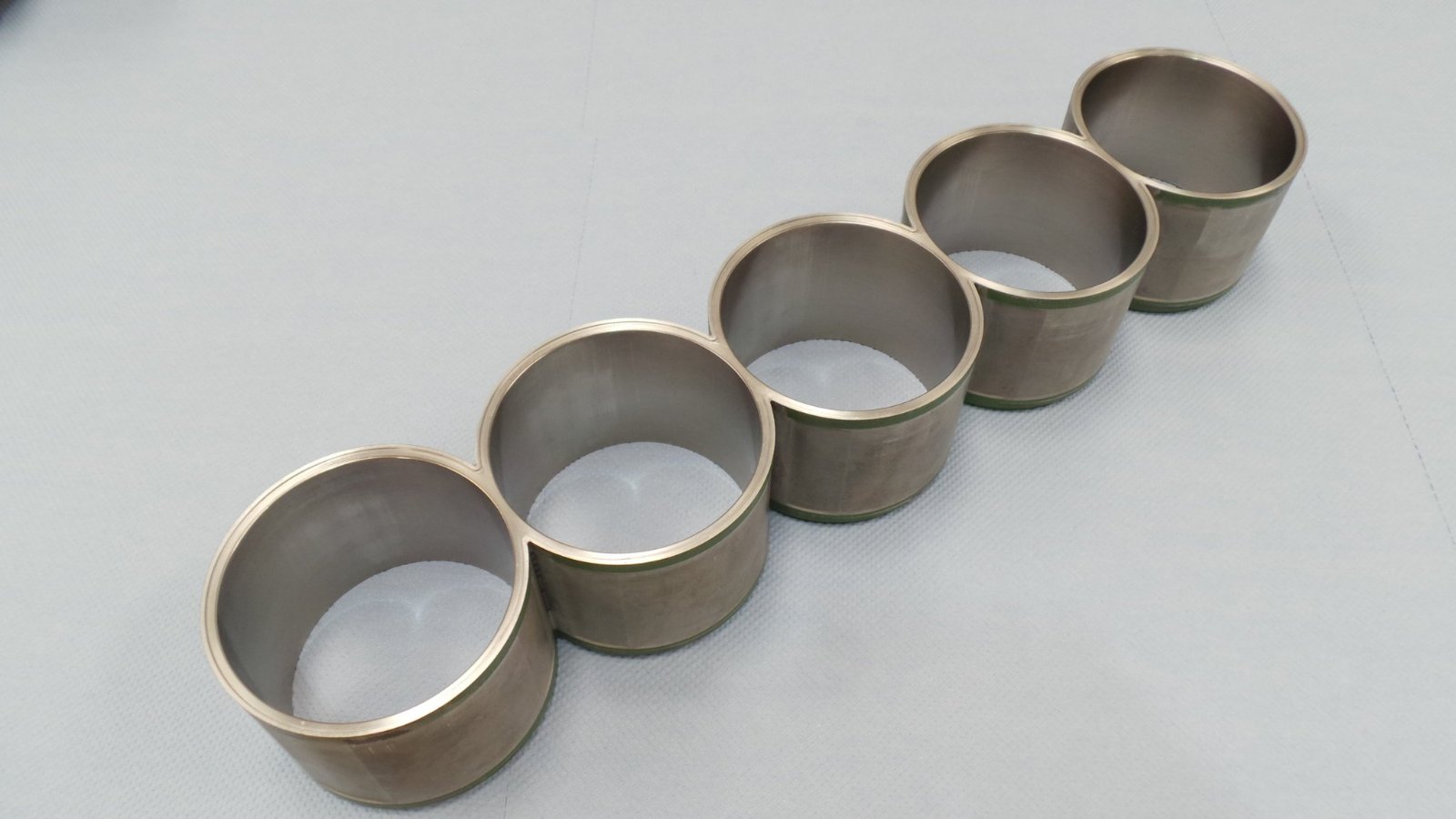
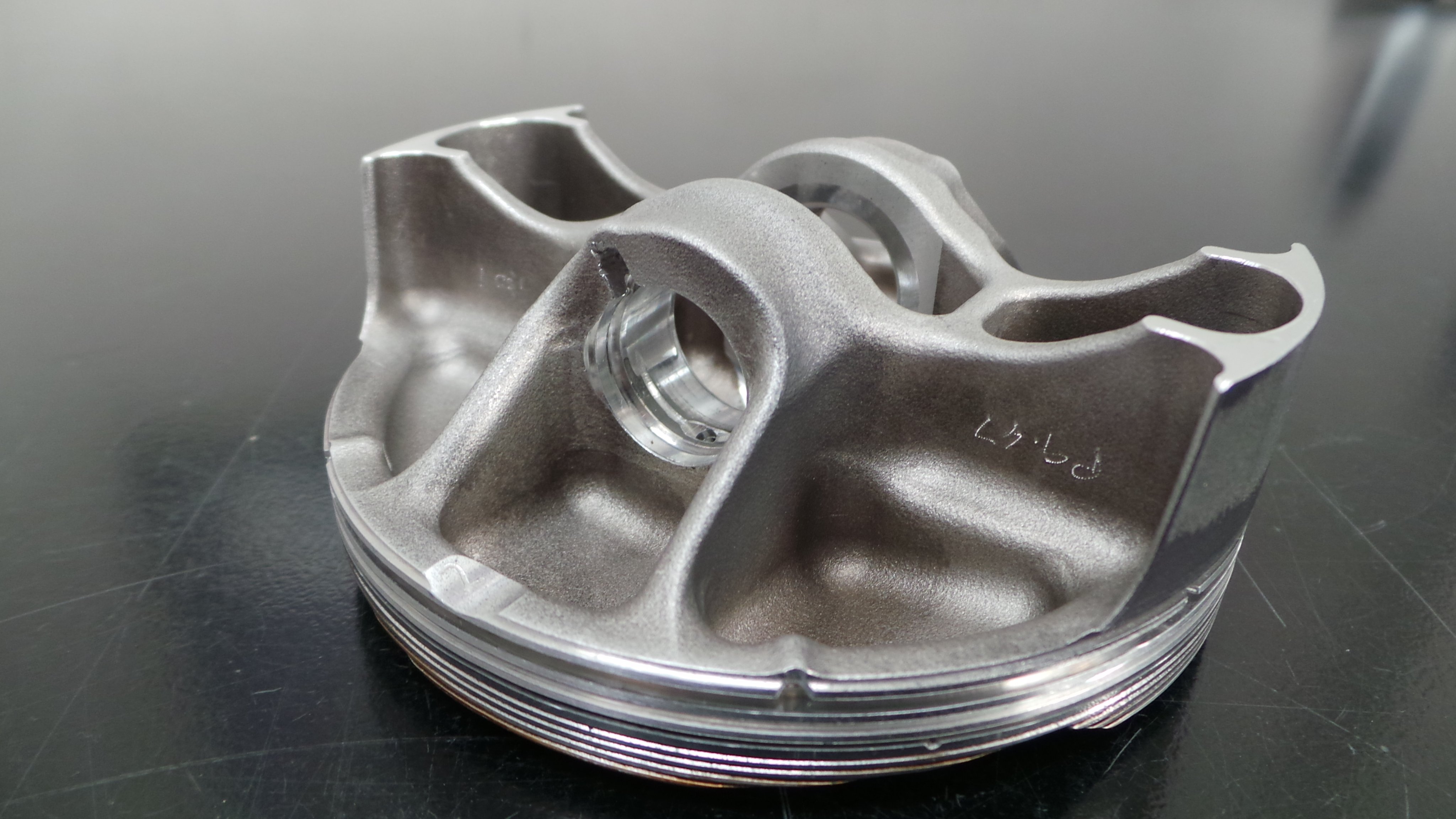
i think ilmor had some very great ideas , e.g not separate but common liners where two cylinders share one wall thickness ( at least in 2001 ) and the general idea to keep the bore lower than competitors to push midrange torque and reduce ring friction .

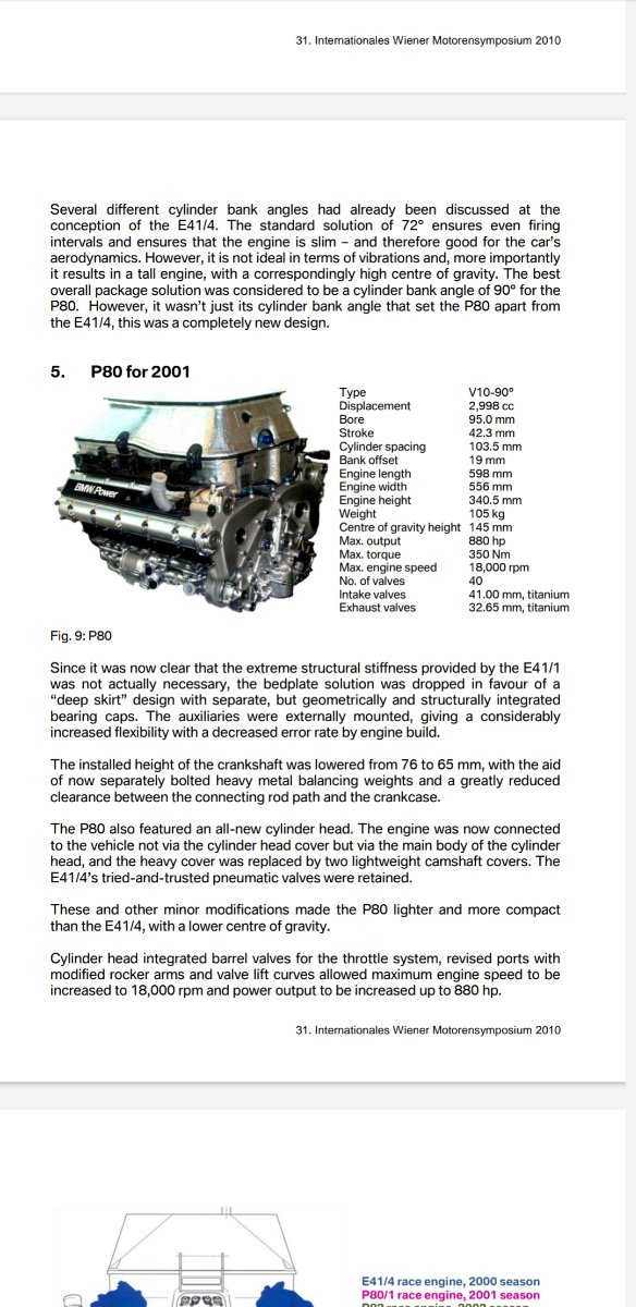
thats why i,m stunned to hear the 2001 ilmor had 95mm bore . it was exactly what major engine manufacturers ran in 2001 ( bmw , honda , cosworth ) and 1mm lower than ferrari which appears to had the most extreme b:s ratio in 2001.

i have only one source of a 1998 72deg ilmor with 93.5x43.67 and believed they did not changed it until 2001 with the 72deg design . if 95mm for 2001 is true i was wrong.
Thanks for posting that ACRO, where does that excerpt come from?
Do you happen to have the rest of the document ?

ACRO
5
Joined: 21 Sep 2006, 22:25

Re: Mercedes V10 F1 Engine - Picture Thread

Post

sure , here it is !

https://www.grandprixengines.co.uk/3rd_ ... Part_2.pdf

i have also solid documents honda had in 2001 95x42.3

Image

and the bmw p80 in 2001 had also a 95x42.3 mm :

Image

all my quessings that ilmor failed in power and reliability 2001 due to the sudden ban of be/al simply because they remained on the idea 'lower bore / higher stroke' BUT with only conventional aluminium pistons that stroke overhelmed material strenght due to piston speeds is gone if i hear now the bore was not really lower than e.g BMW...

User avatar
PlatinumZealot
550
Joined: 12 Jun 2008, 03:45

Re: Mercedes V10 F1 Engine - Picture Thread

Post

What sort of gasket does this use?
Unusual contours on the deck and it doesnt look like an O-ring.. Does the cylinder head have the counter surface to these cuts?

Image

What material are those rockers? Some sort of carbide?
Interesting cantilver design supporting them.

And what are those additional grooves/landings cut around the piston? I know they are not for rings.
I am familiar with these grooves when i was in power industry... But never asked what they were for.
πŸ–οΈβœŒοΈβ˜οΈπŸ‘€πŸ‘ŒβœοΈπŸŽπŸ†πŸ™

ACRO
5
Joined: 21 Sep 2006, 22:25

Re: Mercedes V10 F1 Engine - Picture Thread

Post

@platinum zealot : this engine had wet cylinder liners , but not 5 separate liners per bank like you would expect , instead a common liner pack where two neighboring cylinders share one wall of the liner. due to dawn treader eng this at a massive cost reduced engine lenght for 20mm .

a masterpiece of design i have to admit .

he says this worked only with be/al , after the ban material strenght was overhelmed and they had sealing problems so finally returned to conventional seperate liners.

Image

all information about this and the picture belongs to dawn treader eng

63l8qrrfy6
368
Joined: 17 Feb 2016, 21:36

Re: Mercedes V10 F1 Engine - Picture Thread

Post

PlatinumZealot wrote: ↑
13 Aug 2020, 00:11

What material are those rockers? Some sort of carbide?
Interesting cantilver design supporting them.

And what are those additional grooves/landings cut around the piston? I know they are not for rings.
I am familiar with these grooves when i was in power industry... But never asked what they were for.
The finger follower material is chosen to provide the highest resistance to hertz stress/ rolling contact fatigue which really limits the material choice to either through hardened tool steels or case carburized steels.

The cantilever design was actually considered quite poor. In practice the excitation from exhaust valve actuation would cause the poorly supported pivot shaft to vibrate and shake the inlet follower next to it causing poor inlet valve control. On the V8 they dropped this design for a more conventional arrangement.

I am not quite sure which piston grooves you mean ? The vee shaped groove under the top ring groove or the small groove below the oil ring groove ? The former is a standard accumulator groove while the latter I believe is for oil drain back.

Ringleheim
9
Joined: 22 Feb 2018, 10:02

Re: Mercedes V10 F1 Engine - Picture Thread

Post

These are really nice photos. Thanks for posting.

User avatar
PlatinumZealot
550
Joined: 12 Jun 2008, 03:45

Re: Mercedes V10 F1 Engine - Picture Thread

Post

Mudflap wrote: ↑
13 Aug 2020, 11:08

I am not quite sure which piston grooves you mean ? The vee shaped groove under the top ring groove or the small groove below the oil ring groove ? The former is a standard accumulator groove while the latter I believe is for oil drain back.
The shallow grooves near the crown that favours machine marks.

Image
πŸ–οΈβœŒοΈβ˜οΈπŸ‘€πŸ‘ŒβœοΈπŸŽπŸ†πŸ™

User avatar
PlatinumZealot
550
Joined: 12 Jun 2008, 03:45

Re: Mercedes V10 F1 Engine - Picture Thread

Post

ACRO wrote: ↑
13 Aug 2020, 08:58
@platinum zealot : this engine had wet cylinder liners , but not 5 separate liners per bank like you would expect , instead a common liner pack where two neighboring cylinders share one wall of the liner. due to dawn treader eng this at a massive cost reduced engine lenght for 20mm .

a masterpiece of design i have to admit .

he says this worked only with be/al , after the ban material strenght was overhelmed and they had sealing problems so finally returned to conventional seperate liners.

https://www.directupload.net

all information about this and the picture belongs to dawn treader eng
Thanks. wow.
Why does the parts of the deck around the bore have contours/different levels? would love to see the underside of the cylinder head.
πŸ–οΈβœŒοΈβ˜οΈπŸ‘€πŸ‘ŒβœοΈπŸŽπŸ†πŸ™

User avatar
dren
226
Joined: 03 Mar 2010, 14:14

Re: Mercedes V10 F1 Engine - Picture Thread

Post

PlatinumZealot wrote: ↑
13 Aug 2020, 17:50

Thanks. wow.
Why does the parts of the deck around the bore have contours/different levels? would love to see the underside of the cylinder head.
Same thing I was wondering. I was guessing the head fits within the deck as well.
Honda!

63l8qrrfy6
368
Joined: 17 Feb 2016, 21:36

Re: Mercedes V10 F1 Engine - Picture Thread

Post

PlatinumZealot wrote: ↑
13 Aug 2020, 17:46
Mudflap wrote: ↑
13 Aug 2020, 11:08

I am not quite sure which piston grooves you mean ? The vee shaped groove under the top ring groove or the small groove below the oil ring groove ? The former is a standard accumulator groove while the latter I believe is for oil drain back.
The shallow grooves near the crown that favours machine marks.
Ah, they are meant to be anti detonation grooves.
Probably more of a vestigial feature, they were shown to be completely obsolete in late V10 and V8 engines.

ACRO
5
Joined: 21 Sep 2006, 22:25

Re: Mercedes V10 F1 Engine - Picture Thread

Post

PlatinumZealot wrote: ↑
13 Aug 2020, 17:50
Thanks. wow.
Why does the parts of the deck around the bore have contours/different levels? would love to see the underside of the cylinder head.
i can only quess the cylinderhead has mirrored contours to maximise stiffness and gasket sealing . this engine has surely more secrets to share .

one interesting thing i learned from a now published honda documentation about their f1 V10 engine development :

look at the ilmor crankshaft

Image

do you see the rods inserted in the counterweights ? these are tungsten rods since its one of the highest density material , far more dense than steel and so they reached the needed counterweight mass from a physical much more smaller counterweight.

compare the 2001 ilmor crankshaft to a 2020 crankshaft of a BMW M5 V8 sports car .

Image

i think the late F1 V10 / V8 were from a mechanical point of view the most advanced and extreme piston engines ever made .

saviour stivala
51
Joined: 25 Apr 2018, 12:54

Re: Mercedes V10 F1 Engine - Picture Thread

Post

A four-valve crossflow, single central plug, pent-roof combustion chamber, with extremely narrow included valve angle and at TDC much of the combustion chamber was formed by the pronounced piston crown cut-outs. Required for valve clearance, the compression ratio was in the order of 12.5-13:1. Each aluminium alloy head had an integral tappet-block and a 12 bolt fixing to the block. Bronze rings sealed the wet liners, which were supported by the block in conventional fashion.

User avatar
PlatinumZealot
550
Joined: 12 Jun 2008, 03:45

Re: Mercedes V10 F1 Engine - Picture Thread

Post

Those BMW M5 pistons sure did a good job of the F1 mimicry.
πŸ–οΈβœŒοΈβ˜οΈπŸ‘€πŸ‘ŒβœοΈπŸŽπŸ†πŸ™

e36jon
66
Joined: 25 Apr 2016, 02:22
Location: California, USA

Re: Mercedes V10 F1 Engine - Picture Thread

Post

First off, thanks for posting these amazing photos. It's incredible to see all of the details captured so well.

To me this engine has a consistent and unique aesthetic, with way more flat / faceted surfaces than any other F1 engine I have seen. Specifically, the piston crowns, the conrods, and the way the crank counterweights are bobbed all seem unique to this engine. I can't imagine that there was an industrial designer involved that wanted things to look a certain way, so then something else drove these details. These forms are simpler to machine, but even that seems like not enough reason. Any thoughts on what the driver was?

Again, what a treat to see these parts!

Jon

63l8qrrfy6
368
Joined: 17 Feb 2016, 21:36

Re: Mercedes V10 F1 Engine - Picture Thread

Post

ACRO wrote: ↑
14 Aug 2020, 07:34
one interesting thing i learned from a now published honda documentation about their f1 V10 engine development :
look at the ilmor crankshaft

https://www.directupload.net

do you see the rods inserted in the counterweights ? these are tungsten rods since its one of the highest density material , far more dense than steel and so they reached the needed counterweight mass from a physical much more smaller counterweight.
Cosworth developed an even more effective method of counterweighting by bolting the tungsted to the crank, allowing them to have the high density metal at a larger radius (distance from crank centreline) where it was more effective and as such achieve a lighter crank with the same % balance.

Post Reply