Mercedes Power Unit Hardware & Software

All that has to do with the power train, gearbox, clutch, fuels and lubricants, etc. Generally the mechanical side of Formula One.
User avatar
Blackout
1562
Joined: 09 Feb 2010, 04:12

Re: Mercedes Power Unit Hardware & Software

Post

Mudflap wrote:
15 Feb 2021, 21:26
Thunder wrote:
15 Feb 2021, 20:30
Not Engine Dyno specifically but apparently McLaren shipped their Car to AVL for Dyno testing (Full Chassis Dyno?). Better than nothing for Merc i guess.
Yes, they have been testing in Graz for the last couple weeks.
Is it a common practice in f1 to do full chassis-dyno testing between the first fire-up and the shakedown?

zibby43
613
Joined: 04 Mar 2017, 12:16

Re: Mercedes Power Unit Hardware & Software

Post


Image

Image

63l8qrrfy6
368
Joined: 17 Feb 2016, 21:36

Re: Mercedes Power Unit Hardware & Software

Post

godlameroso wrote:
26 Feb 2021, 04:47
Wouldn't the top blanking plate be the external wastegate/actuator, and the two capped tubes the wastegate pipe flanges?

Very top is for the valve itself, and the forward one is the actuator? I could be wrong.

Or do you mean double wastegates like in this picture?
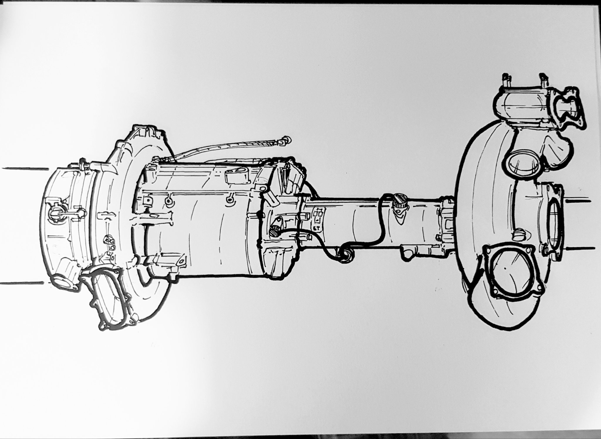
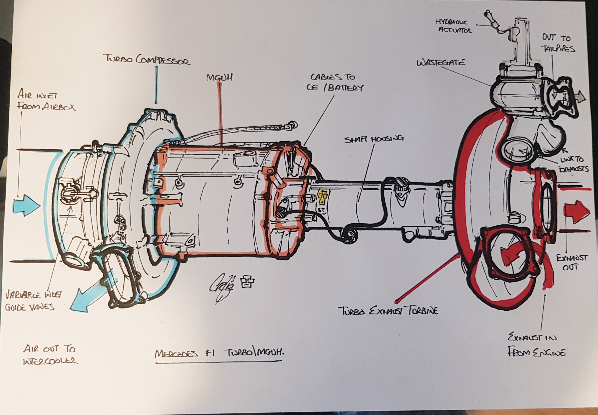
I mean the black blanking plates in the rear engine shot at 1:30 in the video, not the turbo picture.

63l8qrrfy6
368
Joined: 17 Feb 2016, 21:36

Re: Mercedes Power Unit Hardware & Software

Post

Blackout wrote:
26 Feb 2021, 09:38
Mudflap wrote:
15 Feb 2021, 21:26
Thunder wrote:
15 Feb 2021, 20:30
Not Engine Dyno specifically but apparently McLaren shipped their Car to AVL for Dyno testing (Full Chassis Dyno?). Better than nothing for Merc i guess.
Yes, they have been testing in Graz for the last couple weeks.
Is it a common practice in f1 to do full chassis-dyno testing between the first fire-up and the shakedown?
Don't think most customer teams can actually afford it. The big manufacturers will try to get the engine in as early as possible to accumulate mileage in the chassis in parallel with the dyno durability engines.
It doesn't have to be the full chassis though, the most important bits are the transmission/driveline, the cooling system and the hydraulics. It is not unusual for these to be running at the start of the winter.

Poorer customers don't really get more than a rapid prototyped dummy engine for fit checks and a ballasted dummy engine for COG checks.

OO7
OO7
171
Joined: 06 Apr 2010, 17:49

Re: Mercedes Power Unit Hardware & Software

Post

Excellent images from the video. Funnily enough, I'd just asked about the length of MGU-H in another thread just a few days ago and then this video is put out by Mercedes =D> . My original questions were asked because of a concept I've been thinking about for a while and so far the Mercedes MGU-H may already be perfectly designed to fit the concept. I'll bring this up later, perhaps in a different thread.

User avatar
Blackout
1562
Joined: 09 Feb 2010, 04:12

Re: Mercedes Power Unit Hardware & Software

Post

Mudflap wrote:
26 Feb 2021, 11:23
Blackout wrote:
26 Feb 2021, 09:38
Mudflap wrote:
15 Feb 2021, 21:26


Yes, they have been testing in Graz for the last couple weeks.
Is it a common practice in f1 to do full chassis-dyno testing between the first fire-up and the shakedown?
Don't think most customer teams can actually afford it. The big manufacturers will try to get the engine in as early as possible to accumulate mileage in the chassis in parallel with the dyno durability engines.
It doesn't have to be the full chassis though, the most important bits are the transmission/driveline, the cooling system and the hydraulics. It is not unusual for these to be running at the start of the winter.

Poorer customers don't really get more than a rapid prototyped dummy engine for fit checks and a ballasted dummy engine for COG checks.
Thank you for the answers Mudfalp.

hurril
54
Joined: 07 Oct 2014, 13:02

Re: Mercedes Power Unit Hardware & Software

Post

OO7 wrote:
26 Feb 2021, 15:18
Excellent images from the video. Funnily enough, I'd just asked about the length of MGU-H in another thread just a few days ago and then this video is put out by Mercedes =D> . My original questions were asked because of a concept I've been thinking about for a while and so far the Mercedes MGU-H may already be perfectly designed to fit the concept. I'll bring this up later, perhaps in a different thread.
Please do!

I find the pictures very interesting because I've yet to really understand the supposed big difference in shaft length. My thinking has been that summing up the "length" of the MGU-h, the turbine and the compressor would be roughly the same with the MGU-h in front or behind the compressor.

But as this displays, there is a decent difference. So very very interesting!

63l8qrrfy6
368
Joined: 17 Feb 2016, 21:36

Re: Mercedes Power Unit Hardware & Software

Post

There's other aspects too.
With the MGUH in front of the compressor the shaft has to pass through the impeller eye. Combined with the sharp turn at the compressor inlet present in all configurations the flow distribution to the inducer will be poorer and the pressure drop higher compared to configurations where the MGUH is behind the compressor.

The inlet pressure drop is amplified by the compressor pressure ratio (in excess of 4) so the effect is quite significant.

hurril
54
Joined: 07 Oct 2014, 13:02

Re: Mercedes Power Unit Hardware & Software

Post

Mudflap wrote:
27 Feb 2021, 18:04
There's other aspects too.
With the MGUH in front of the compressor the shaft has to pass through the impeller eye. Combined with the sharp turn at the compressor inlet present in all configurations the flow distribution to the inducer will be poorer and the pressure drop higher compared to configurations where the MGUH is behind the compressor.

The inlet pressure drop is amplified by the compressor pressure ratio (in excess of 4) so the effect is quite significant.
This is not something that I've heard of before. Would you like to explain more or direct me someplace to read more about it?

63l8qrrfy6
368
Joined: 17 Feb 2016, 21:36

Re: Mercedes Power Unit Hardware & Software

Post

Simply put if the MGUH is ahead of the compressor there has to be a shaft passing through the air inlet. This shaft will disturb the airflow.

In the image below you can see the large oval compressor inlet with a 90 degree turn and the MGUH flange. The shaft is not shown but it has to pass through the inlet.
Image

The disadvantages of a shaft through the compressor eye were noted as far back as ww2 - the first that comes to mind is the napier nomad but there are some other notable examples.

Image

hurril
54
Joined: 07 Oct 2014, 13:02

Re: Mercedes Power Unit Hardware & Software

Post

I should have been more precise (although I really appreciate this anyway!) I was interested in what you said about the pressure drop in front of a compressor, especially when the pressure ratio surpasses about 4.

63l8qrrfy6
368
Joined: 17 Feb 2016, 21:36

Re: Mercedes Power Unit Hardware & Software

Post

That's straightforward - boost pressure is inlet pressure times PR. If there's say 50 milibar loss at the inlet that translates to a 50x4 milibar loss in boost pressure.
Last edited by 63l8qrrfy6 on 28 Feb 2021, 04:09, edited 2 times in total.

Jolle
132
Joined: 29 Jan 2014, 22:58
Location: Dordrecht

Re: Mercedes Power Unit Hardware & Software

Post

The split turbo solution looks so logical now, can’t think of a single big advantage to have the Renault or Ferrari solution.

User avatar
PlatinumZealot
550
Joined: 12 Jun 2008, 03:45

Re: Mercedes Power Unit Hardware & Software

Post

The inlets for the mguh infront of the compressor usually are very large to compensate for the energy losses to. You see very wide bean-shaped inlets pointing upward to allow space to initiate the swirling motion.

I even wonder if those configurations manage to fit a variable vaned inlet?
🖐️✌️☝️👀👌✍️🐎🏆🙏

OO7
OO7
171
Joined: 06 Apr 2010, 17:49

Re: Mercedes Power Unit Hardware & Software

Post

PlatinumZealot wrote:
27 Feb 2021, 23:46
The inlets for the mguh infront of the compressor usually are very large to compensate for the energy losses to. You see very wide bean-shaped inlets pointing upward to allow space to initiate the swirling motion.

I even wonder if those configurations manage to fit a variable vaned inlet?
If you mean the guide vanes directly ahead of the compressor inlet, the Mercedes certainly has these. I think they're used for "throttling" and there's a picture somewhere showing the Mercedes installation.

Post Reply