- Login or Register
No account yet? Sign up

Team: Bob Bell (TD), Norbert Haug (VP of Mercedes-Benz Motorsport), Nick Fry (CEO), Ross Brawn (TP), Geoff Willis (Technology Director), Also Costa (Engineering Director)
Drivers: Michael Schumacher (7), Nico Rosberg (8)

It's not so much about the volume added, but the energy of the air flowing through that section – if you can get it going faster, at lower preasure than the rest of the diffuser then you'll suck air out of the diffuser and make all of it operate more efficiently.Ferraripilot wrote:Has anyone done a CFD model on the starter hole blown diffuser addition? I find myself constantly wondering how much their small volume addition to their diffuser adds.
beelsebob wrote:It's not so much about the volume added, but the energy of the air flowing through that section – if you can get it going faster, at lower preasure than the rest of the diffuser then you'll suck air out of the diffuser and make all of it operate more efficiently.Ferraripilot wrote:Has anyone done a CFD model on the starter hole blown diffuser addition? I find myself constantly wondering how much their small volume addition to their diffuser adds.

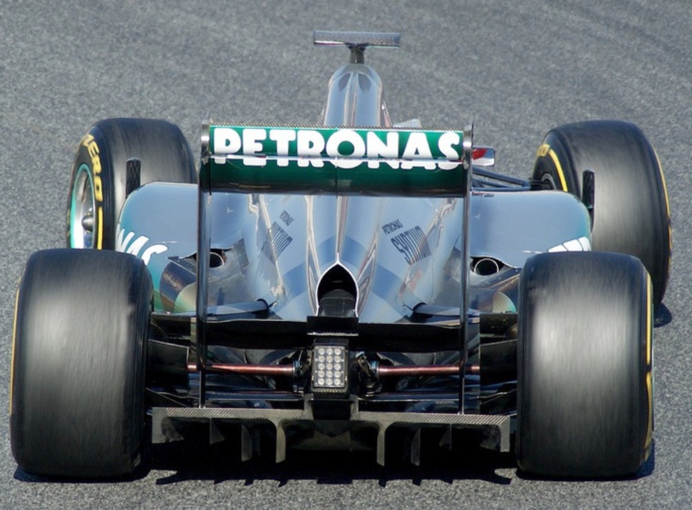
Owen.C93 wrote:Just to clarify that isn't a starter motor hole. It's just where they've placed two sides below the crash structure to make a little outlet. It looks like they've used the RBR style ducts to feed that make shift hole rather than utilising an oversize starter motor hole lower down on the diffuser.
Nickel wrote:Owen.C93 wrote:Just to clarify that isn't a starter motor hole. It's just where they've placed two sides below the crash structure to make a little outlet. It looks like they've used the RBR style ducts to feed that make shift hole rather than utilising an oversize starter motor hole lower down on the diffuser.
So this outlet is fed by air above the floor?
This is xactly what I mean, if it looks right, it most probably is right.Blackout wrote:Another photo on the ducted cooling outlet and the diffuser
Yes it looks like it, you can see some ducts in some other photos.Nickel wrote:Owen.C93 wrote:Just to clarify that isn't a starter motor hole. It's just where they've placed two sides below the crash structure to make a little outlet. It looks like they've used the RBR style ducts to feed that make shift hole rather than utilising an oversize starter motor hole lower down on the diffuser.
So this outlet is fed by air above the floor?
The starter motor hole is that little circle further down.Ferraripilot wrote:Nickel wrote:Owen.C93 wrote:Just to clarify that isn't a starter motor hole. It's just where they've placed two sides below the crash structure to make a little outlet. It looks like they've used the RBR style ducts to feed that make shift hole rather than utilising an oversize starter motor hole lower down on the diffuser.
So this outlet is fed by air above the floor?
There was some conjecture earlier that might be the case, but I doubt it's blown by anywhere other than the starter hole. Still difficult to say though.
And this is LEGAL? [-o<Crucial_Xtreme wrote:About the W03's exhaust & diffuser. AutoSport's Gary Anderson say that Mercedes is doing this:
The W03 appears to use the hot air from the exhausts & the cooling outlet at the base of the engine cover, directing it towards the upper surfaceof a central section of the diffuser. This section is partly formed from the underside of the crash structure in a similar way to what we saw during the double diffuser days. But instead of being fed airflow through the now banned slots in the flow, it takes it from the flow energized by the differing pressures of hot air flowing over it and cool air through it. Enhancing the effect are the curved splitters(strakes)within the diffuser, which appear to be for turning the airflow coming through it towards that raised central section.

