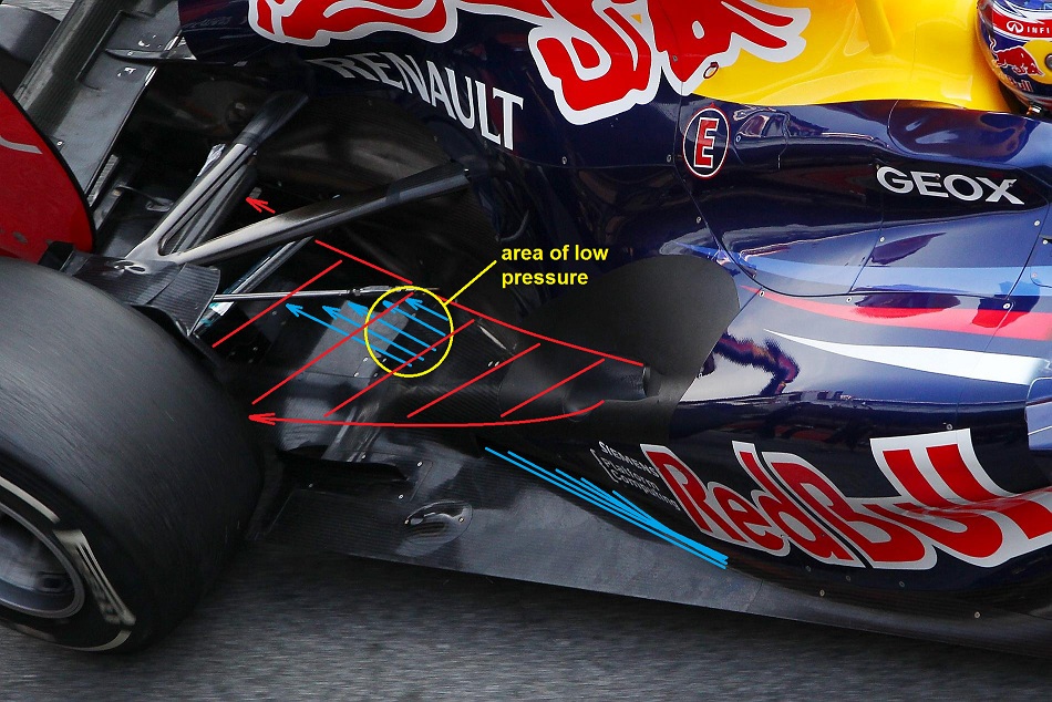
I like everything about this idea except for two things: If you can seal the diffuser, the effect of the downforce is multiplied by the amount of the seal - resulting in much more bang for your buck. And, Adrian Newey installed a channel in the sidepod to direct as much of the exhaust flow as he could to outside of the sidepod. I believe he did this for a reason.gandharva wrote:Here is my theory... Could it be that this tunnel works like a chimney?
The exhaust gases flow down the sidepod just over the rear end of the tunnel creating an area of low pressure and thus sucking more air through the tunnel. This could lead to more air on top of the floor plate which could be used to create downforce on e.g. the lower rear wing.
Without the tunnel, I think the exhaust gases would create some sort of barrier and this would lead to less air that could get routet in the direction of the rear wing.
Some shitty picture to "proof" my theory. XD
[img]http://www.abload.de/img/testyijsp.jpg[img]
- Login or Register
No account yet? Sign up