Ferrari F138

A place to discuss the characteristics of the cars in Formula One, both current as well as historical. Laptimes, driver worshipping and team chatter do not belong here.
bill shoe
bill shoe
151
Joined: 19 Nov 2008, 08:18
Location: Dallas, Texas, USA

Re: Ferrari F138

Post

Lorenzo_Bandini wrote:The nose of this car is very high. The Ferrari looks like a tank

Image
I think Ferrari have done a clever rule interpretation that no other team figured out, or at least put into practice. Hypothesis-- The structural part of the front of the Ferrari nose consists of two longitudinal tusks that form the upper parts of the wing pylons. The vanity cover is actually the entire connection between the upper wing pylons. This means the leading edge of the nose (between the pylons) is entirely part of the vanity cover, and is higher than the allowable structural height. If true then this would increase the nose height and thus the airflow under the nose. It would not increase the allowable height under the main chassis, but it would allow more initial flow under the nose. This could also explain the slightly awkward shape of the leading edge of the upper pylons.

I don't really see any other way the Ferrari nose could be so much higher than the Red Bull. The RB is not leaving much on the table, meaning their nose is about as vertically thin as is practical. And yet the Ferrari nose is significantly higher. Look at some other close-up pics of the Ferrari nose tip and see what you think. One of the criticisms of Ferrari in recent years is lack of creative rule interpretation. The new nose is a potential example of clever and strong thinking to the contrary.


User avatar
ecapox
8
Joined: 14 May 2010, 21:06

Re: Ferrari F138

Post

bill shoe wrote:
Lorenzo_Bandini wrote:The nose of this car is very high. The Ferrari looks like a tank


I think Ferrari have done a clever rule interpretation that no other team figured out, or at least put into practice. Hypothesis-- The structural part of the front of the Ferrari nose consists of two longitudinal tusks that form the upper parts of the wing pylons. The vanity cover is actually the entire connection between the upper wing pylons. This means the leading edge of the nose (between the pylons) is entirely part of the vanity cover, and is higher than the allowable structural height. If true then this would increase the nose height and thus the airflow under the nose. It would not increase the allowable height under the main chassis, but it would allow more initial flow under the nose. This could also explain the slightly awkward shape of the leading edge of the upper pylons.

I don't really see any other way the Ferrari nose could be so much higher than the Red Bull. The RB is not leaving much on the table, meaning their nose is about as vertically thin as is practical. And yet the Ferrari nose is significantly higher. Look at some other close-up pics of the Ferrari nose tip and see what you think. One of the criticisms of Ferrari in recent years is lack of creative rule interpretation. The new nose is a potential example of clever and strong thinking to the contrary.
Like this. Discussed on page 14 of this thread.

Image

heho07
heho07
1
Joined: 30 Jun 2012, 22:20

Re: Ferrari F138

Post

Can anyone answer my questions:
1-Why and how air inside red rectangular goes outside as i show them with red arrows.
2-How circle like shape appear on the floor?is it where exhaust gas hit the floor?
3-Why blue arrows start from red rectangular?
Thanks.

Sorry for my bad English.

Image
Last edited by heho07 on 08 Feb 2013, 04:34, edited 1 time in total.

bill shoe
bill shoe
151
Joined: 19 Nov 2008, 08:18
Location: Dallas, Texas, USA

Re: Ferrari F138

Post

Yea, I didn't see that. :oops: It's 80% of what I said. The difference is I think Ferrari's vanity panel does not extend forward of a conventional flat/wide nose like the sketch, but rather the vanity panel extends directly up from the parallel walrus tusks. We need a Ferrari to nose into a wall so we'll get a good look.

Crucial_Xtreme
Crucial_Xtreme
404
Joined: 16 Oct 2011, 00:13
Location: Charlotte

Re: Ferrari F138

Post

heho07 wrote:Can anyone answer my questions:
1-Why and how air inside red rectangular goes outside as i show them with red arrows.
2-How circle like shape appear on the floor?is it where exhaust gas hit the floor?
3-Why blue arrows start from red rectangular?
Thanks.

Sorry for my bad English.
The red rectangle is going to be "spillage". The green circle is actually a sensor, check other pics w/out Flo-Vis or the RB9 for instance.
I cannot explain the blue arrows.

I'd be interested to see Flo-Vis with the new strakes & top/cover just ahead of the rear tyres. Floor slots for tyre squirt are still present.

Image

sknguy
sknguy
3
Joined: 14 Dec 2004, 21:02

Re: Ferrari F138

Post

jaba.hut wrote:For as precise as possible check they use constant speed laps. Those data is closest to wind tunnel. Ferrari said last year said that simulation and designing exhaust gases in wind tunnel is hard and also in CFD simulations. I think that gives you some explanation to your question.
I guess that's where one has to leave it then. It's simply very difficult for the windtunnel to give a clear enough feedback on all the variables. Since it's that tough for Ferrari to do with a windtunnel then hats-off to those who would endeavoured to do development or design work heavily in CFD alone. Thanks for the reply.

sknguy
sknguy
3
Joined: 14 Dec 2004, 21:02

Re: Ferrari F138

Post

heho07 wrote: 3-Why blue arrows start from red rectangular?
Thanks.

Sorry for my bad English.
Would this not be the low pressure area behind the airbox/rear of sidepod and closer to the floor drawing air in towards the center?

ADDED: and the high pressure area ahead of the rear wheel too I suppose.

User avatar
Kiril Varbanov
147
Joined: 05 Feb 2012, 15:00
Location: Bulgaria, Sofia

Re: Ferrari F138

Post

heho07 wrote:Can anyone answer my questions:
3-Why blue arrows start from red rectangular?
They do not, necessarily. This is just how it looks like, but this is generally the area where the exhaust flow, the under-sidepod flow mix together. The later pushes air inboard, hence the direction of the flow-viz, blue arrows. One of other pushers are the voritces that come from the front part of the floor, where Ferrari have this curved element. And although this is relatively weak vortex, it still has its momentum, but of course, it doesn't "burst", still, it's an upwash movement enough to divert air.

Crabbia
Crabbia
9
Joined: 13 Jun 2006, 22:39
Location: ZA

Re: Ferrari F138

Post

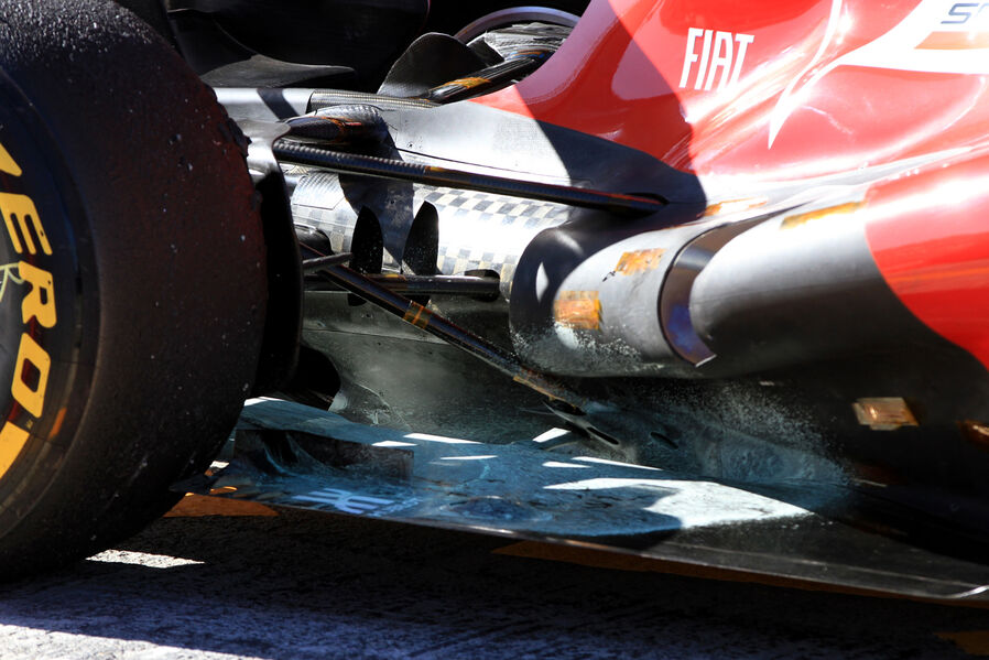
just had a look at this picture. look how neat the pull rod pick up point is compared to last year. it has a little shroud around it.

Also, am i seeing things or are those vertical strakes just below the pull rod, pointing inwards at a 45° ish angle?

zoom and enhance people.
A wise man once told me you cant polish a turd...

User avatar
Lurk
2
Joined: 13 Feb 2010, 20:58

Re: Ferrari F138

Post

ecapox wrote:
bill shoe wrote:
Lorenzo_Bandini wrote:The nose of this car is very high. The Ferrari looks like a tank


I think Ferrari have done a clever rule interpretation that no other team figured ou[...]
Like this. Discussed on page 14 of this thread.
https://dl.dropbox.com/u/5521387/Nose_625.jpg
Or...
Image
Rollhoop at 95cm, chassis height estimated at 63cm (rules specifies 62,5cm so 0.5cm of error) and tip height estimated at 52cm.
Thx to Mechanix @ ToileF1.


On the F138 vs RB9 image, the RBR has clearly more rake than the Ferrari: T-cam nearly as same height than RW and FW clearance is way smaller.

.poz
.poz
50
Joined: 08 Mar 2012, 16:44

Re: Ferrari F138

Post

I don't know if someone already spotted this...

Cooling exit with aerodynamic function ? or just reflection/shadow ?

Image

.poz
.poz
50
Joined: 08 Mar 2012, 16:44

Re: Ferrari F138

Post

Blue arrows are just junction on carbon fiber floor

Image

Image

Crabbia
Crabbia
9
Joined: 13 Jun 2006, 22:39
Location: ZA

Re: Ferrari F138

Post

I disagree, good spot, but the arch of the flow vis starts ahead of the vertical strake in the top picture.

The arch of the panel starts below the strake in the second picture.

I think they designed that floor panel to follow the intended shape of the flow in that area, to mininmise boundary layer influence, but i dont think it the panel is what is shown in the first picture.

I think the panel you are refering to is hidden behind the vertical strake in the first picture.
Image

If you look closely in this picture you can see the panel you are refering to as well as the flow viz mark.

edit for picture.
A wise man once told me you cant polish a turd...

PsychdbyF1
PsychdbyF1
0
Joined: 04 Jul 2011, 10:22
Location: Bangalore, IND

Re: Ferrari F138

Post

sknguy wrote:Just wondering.... I assume that all the data gathered at these test sessions is also used for the simulator. I also assume the data will be compared/correlated with the wind tunnel's own data. And that both data sets are used to improve the modeling in their simulators. What I'm curious about though is how closely the wind tunnel data matches real world data. Granted there's so many variables in real world that just aren't there in a windtunnel. I suppose that for one thing Ferrari likely doesn't have a motor running with hotgasses exhausting at 18,000 rpm in the tunnel. But the F2012 had such dissapointing results in real world performance because the data probably wasn't showing them that. But I'm assuming the windtunnel data would be pretty darn comprehensive. Curious indeed...
There's a pretty good, (although insufficient with respect to the level of detail! ;-)), explanation by James Allison which I've quoted here --> http://psychdbyf1.wordpress.com/2012/08 ... -exhausts/

It talks about what you are referring to - "hot gases exhausting at 18000 rpm in the tunnel". They obviously can't have a 60% engine running in the wind tunnel, and hence they probably take cold flow measurements in the tunnel as he says in his interview, and they also use test sessions to map the actual exhaust flow using sensor arrays. Then these two sets of data are correlated.
See the sensor array pic here --> http://psychdbyf1.wordpress.com/2012/10 ... -downwash/
would be glad if someone could actually elaborate more on wind tunnels w.r.t the exhaust flow! [-o<

diemaster
diemaster
6
Joined: 07 Jun 2012, 16:59

Re: Ferrari F138

Post

Image
Image
Image